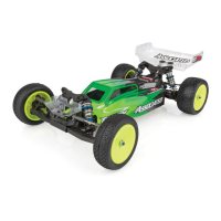
D
Fig.
7 4
Now
we'll
be
assembling
these parts, in the
order shown, onto the shaft. First.
insta
ll
the
#6901 ball
bearing from
Bag
B into the #6584
clutch
hub, and then
slide
the hub onto the shaft, making sure the
clutch
disk
stays centered
on
the hub.
From Bag
F,
install
one of the #6586 thrust wash-
ers. then the thrust bearing and the other thrust washer.
(NOTE:
when servicing this thrust bearing you can use a
very
little
of
the #6588
black
grease.)
N
ow
slip
the #6587 spring
on
and
start the 5-40
nut
on. Tighten the nut
until
about
1/2 thread is showing
outside the nut. This is a
good
starting point for the
clutch
adjustment.
If
the
ball
bearing in the
clutch
hub
will
not
slip
onto the shaft, then you have not used the correct bearing
described in fig. 38.
Disasse
mble
the
diff
and
install
the
correct bearing.
6901
6587
~wA
6584
6586
Fig.
74
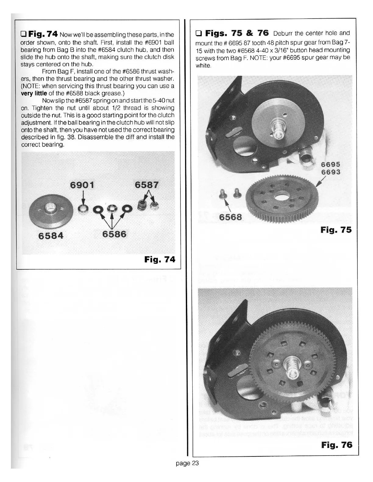
D
Figs.
75
&
76
Deburr the
cen
ter
hole
and
mount the # 6695 87 tooth
48
pitch
spur
gear
from
Bag
7-
15
wi
th the two #6568
4-40 x
3/16" button head mounting
sc
rews fr
om
Bag F.
NOTE:
your #6695
spur
gear
may
be
white.
6568
Fig.
75
Fig.
76
page
23