6474
7435
6431
11.30mm
r
6471
Fig
.
121
0 Fig.
122
On
the front shocks,
install
the
spring
collars,
as shown. Use the short
gold
spring
s.
6432
7425
Fig.
122
0
Figs.
123
&
124
From Bag
7-1
take one of
the
long
#7
420 4/40
x
5/8" Special SHCS
screws that has
threads on the end only. Slip
the shaft end of the right hand
front shock into the
slot
of
the front A-arm, as shown. make
sure
the
flat flange
of
the
steel ball
is towards the rear.
Install the screw in the dire
ct
ion t
he
arrow shows. Do the
left
hand side.
Fig.
123
page
33
Fig.
124
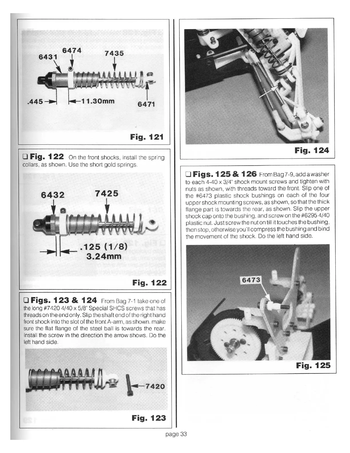
0
Figs.
125
&
126
From Bag 7-9,
add
a washer
to each
4-40 x 3/4"
shock mount screws and tighten with
nuts as shown, with threads toward the front. Slip
one
of
the #6473
plastic
shock bushings on each
of
the fo
ur
u
pper
shock mounting screws, as shown, so that the t
hick
flange
part is towards the rear, as shown.
Slip the u
ppe
r
shock
cap
onto the bushing, and screw on the #6295 4/40
plastic
nut. Just
screw
t
he
nut on
till
it touches the bushing,
then stop, otherwise
you'll
compress the bushing and bind
the movement
of
the shock. Do the
left
hand
side.
Fig.
125