0
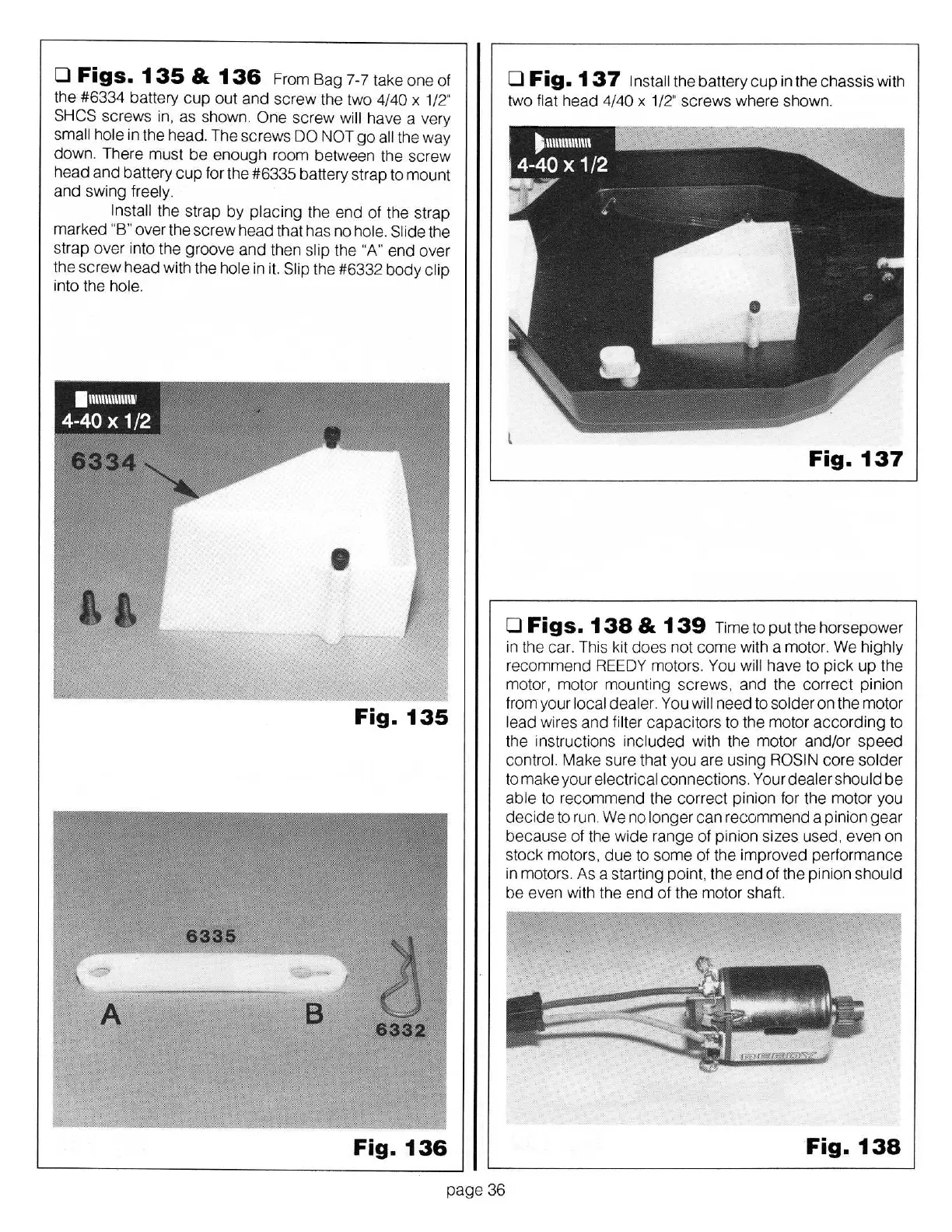
Figs.
1
35
&
136
From Bag 7-7 take
one
of
the #6334 battery
cup
out and screw the two 4/40
x
1/2"
SHCS
sc
rews in, as shown.
One
screw
will
have a very
sma
ll
hole
in the head. The
sc
rews
DO
NOT
go
al
l
the way
down
. There must
be
enough room between the screw
head
and
battery
cup
for the #6335 battery str
ap
to mount
and
swing
fr
ee
ly.
Install
the
str
ap
by
placing
the end of the
st
r
ap
marked
"B"
over the
screw
head that has no
hole. Slide
the
st
r
ap
over into the groove a
nd
then
slip
the "A"
end over
the
screw
head with the hole
in it.
Slip
the #6332 body
clip
into the
hole.
Fig.
135
Fig.
136
0
Fig.
137
Install
the
ba
ttery
cup
in the chassis with
two
flat
head
4/40
x
1/2" screws
whe
re shown.
Fig.
137
0
Figs.
138
&
139
Ti
me
to put the
ho
rsepower
in the car. This kit does not come with a motor. We
highly
r
ec
ommend REEDY motors. You will
have to
pick
up
the
motor, motor mounting screws. and the correct pinion
from your
local dealer. You
will need to
solder
on the motor
lead
wires
and
fi
lter
capacitors to the motor
acco
rding to
the instructions
included
with the motor and/or
speed
control. Make sure that
yo
u are using ROSIN
co
re
sol
der
to
make your
electrical connec
ti
ons. Your
dea
ler should
be
able
to recommend the
co
rr
ect
pinion for the motor
yo
u
decide
to run. We no
longer
can recommend a pinion
gear
because of the wide range
of
pinion sizes used. even
on
stock motors.
due
to some
of
the improved performance
in motors. As a sta
rt
ing point, the end of the pinion
should
be even with the end of the motor shaft.
Fig.
138
page 36