7
Accurate Sensors Technologies
AST
The pyrometer measure temperature by receiving heat radiation, from the object, whose temperature has to be
measured. This heat radiation is passes through the lens to the sensor and is then converted to an electrical signal.
The farther the measured object is from the pyrometer, the larger the area that will be measured by the pyrometer.
Depending on customer need, the pyrometer is designed for different FOV. User has to select the FOV while ordering.
Contamination on lens will cause inaccurate temperature reading therefore air purge unit is used for sensor head.
Cleaning with dry cloth is sufficient for lens cleaning.
5.1 Optical specification
Chapter-5
Optics
*FOV mentioned on the pyrometer.
For example: If pyrometer FOV is 15:1, then spot size at 1500mm calculated as given below method except that
minium spot should be 6mm.
Installed Spot Size =
Installed Working Distance
FOV
1500
15
=
= 100mm
6
100
200
350
500
200
400
700
1000
2000
1000
0
FOV-2:1
6
14
27
47
67
200
400
700
1000
2000
133
0
FOV-15:1
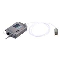
5.2 Exchange of the Sensing Head
From factory side the sensing head has already been connected to the electronics and the calibration code has been
entered.
Entering of the Calibration Code
Every head has a specific calibration code, which is printed on the
head. For a correct temperature measurement and functionality of
the sensor this calibration code must be stored into the electronic box.
The calibration code consists of 4 blocks with 4 digit values.
Example:
For entering the code please press the Function Key and select PSW
option, then write 0011 at PSW by using UP & DOWN key and press the
Function Key to enter into calibration data of Sensing Head.
Now, the display shows 4 Digit of the first block (Block A) with UP and
DOWN key, value can be Change and press Function Key to save.
Switches to the next block and repeat same process for next Block.
3045
Block D
2085
Block C
1040
Block B
1040
Block A