6
Accurate Sensors Technologies
AST
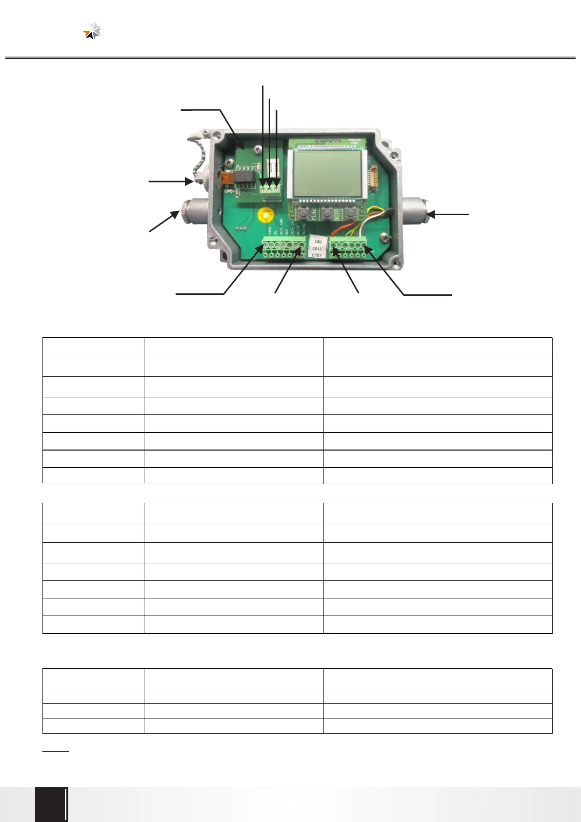
4.4 Pin assignment
Connector pin assignment:
Note : 1. For Analog output, DC supply (+24V DC) is must given to pyrometer first.
2. Pyrometer stabilization time is at least 15 minutes, when ambient temperature is changed.
Pin number
Indication Descriptions
Pin number
Indication Descriptions
X
GND
RS-232 / RS-485 GND
Y
Rx/D+
Rx(RS-232) / D+(RS-485)
Z
Tx/D-
Tx(RS-232) / D-(RS-485)
Optional (RS-232 / RS-485) PCB Connection
Connector
Pin No. 1
Connector
Pin No. 7
USB Output
24V DC input analog
& digital output cable
Sensor cable
Pin No. Z
Pin No. Y
Pin No. X
Optional (RS-232 / RS-485)
Connection PCB
Connector
Pin No. 8
Connector
Pin No. 13
7
RL1-NO
Relay terminal 1
6
RL1-C
Relay terminal 1
3
Out mA(+)
Analog output current (+)
2
0 V
DC supply GND
1
+24 V
DC supply
5
Out V/mV (+)
Analog output voltage/T/C output (+)
4
Out mA/V/mV (-)
Analog output current/ /T/C output (-)voltage
Pin number
Indication Colour Code
13
W
White
10
G
Green
9
R
Not Connected
8
O
Orange - Earthing
12
B
Brown
11
Y
Yellow