72
Adjustments
Flow Switch Adjustment
(Gen.2LubricationSystem
only)
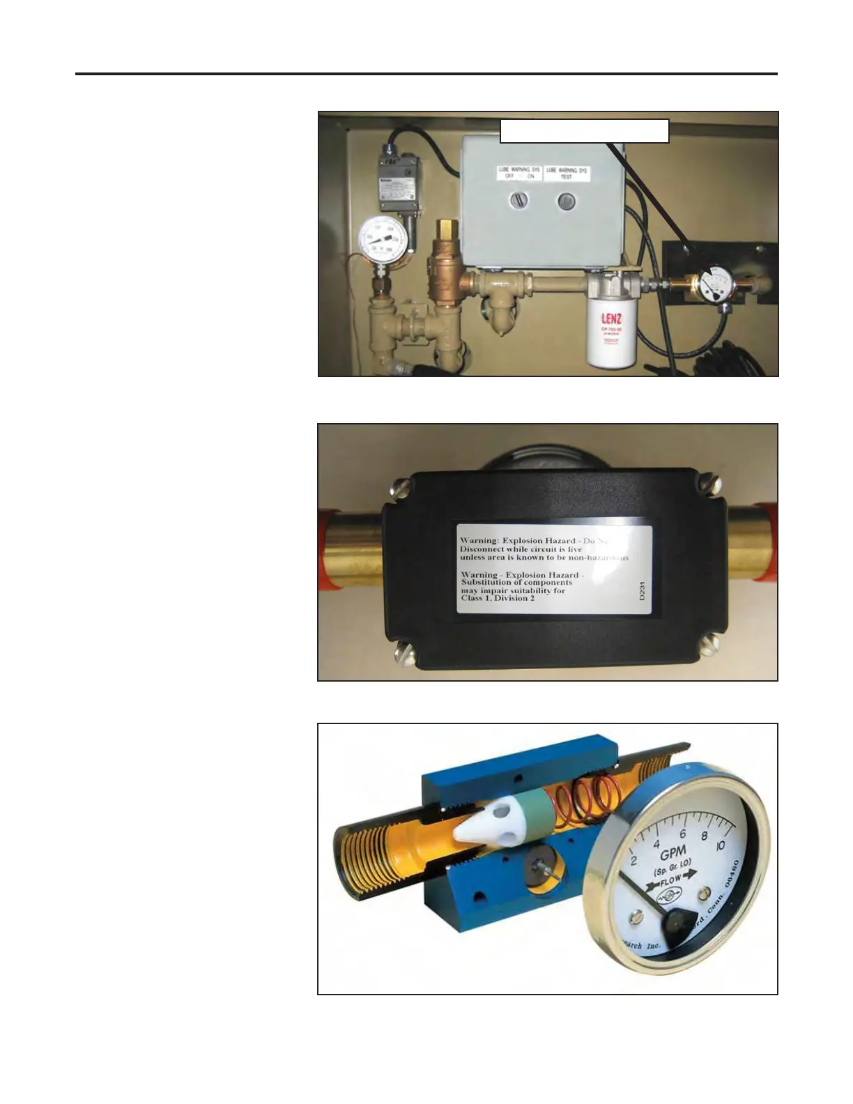
The ow switch monitors oil
flow through the lubrication
system. The process fluid
ows through the ow switch
meter at a rate of 1-3.5 GPM.
The ow causes the sensor,
a spring loaded cone/magnet
assembly, to move from a
large precision orifice. As
flow increases, the sensor
magnet moves toward the
pointer magnet and causes
the reed switch to actuate.
The cone-orice combination
results in variable area ow
measurements and an easy-
to-read linear scale. The reed
switch alerts the operator of
problem conditions.
The flow switch can be
adjusted as needed. Use the
following procedure to adjust
the ow switch.
1.
Lockout/tagout all power to
the vertical shaft impactor.
2. Remove the flow switch
assembly from the
lubrication panel by
disconnecting it at the inlet
and outlet ports.
3. Remove all four screws
from the back panel of the
ow switch.
Flow switch and gauge
Lubrication Panel
Back Cover of Flow Switch
Cross Section of Flow Switch