* Above electrical wiring diagram only for your reference, please subject machine posted the wiring diagram.
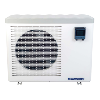
6.6 Installation of the remote display
Photo(1) Photo(2) Photo(3) Photo(4)
- The side with plug connects with the control panel (photo1)
- The other side of the signal wire. (photo2)
- Open the cover of the terminal box and pass through it the cable of the remote screen. (photo3,)
- Insert the wiring into the designated position (upper right corner) on the Modbus Module. (photo4)
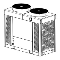
6.7 Installation of the Modbus Signal Wire
Photo(5) Photo(6) Photo(7)
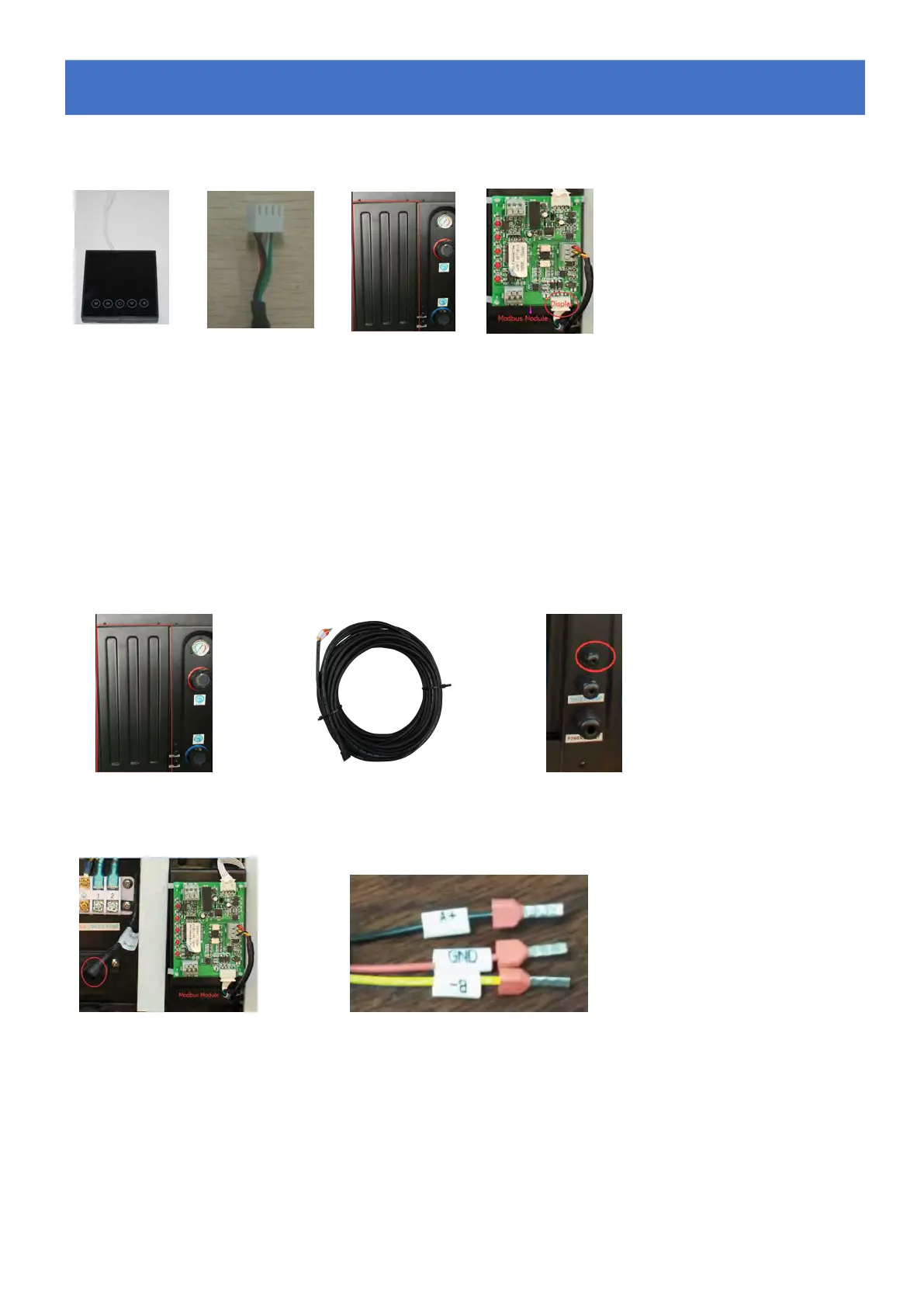
Photo(8) Photo(9)
- Open the Back panel (photo5)
- Take the Modbus signal wire from the accessories (photo 6) and put the one end through the hole (Photo 7)
- Put the round end of the signal wire into the designated position. (photo 8)
- Three wire terminal :
“
A+
”
,
“
B-
”
,
“
GND
”
(Photo 9)
6.
6.
6.
Electrical
Electrical
Electrical
Wiring
Wiring
Wiring