ATTENTION :
Disconnect: A means to disconnect should be located within sight of and readily accessible from the
unit(circuit breaker, fused or un-fused switch). This is common practice on commercial and
residential heat pumps. It prevents remotely-energizing unattended equipment and permits turning
off power at the unit while the unit is being serviced.
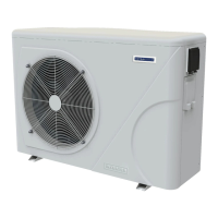
6.7 Installation of the display deportee
Photo(1) Photo(2) Photo(3) Photo(4) Photo(5)
- The end with plug connects with the control panel (photo1)
- The other end of the signal wire. (photo2)
- Open the cover of the terminal box and pass through it the cable of the remote screen.(photo3,4)
- Insert the wiring into the designated position on the Modbus Module or PCB(without Modbus). (photo5)
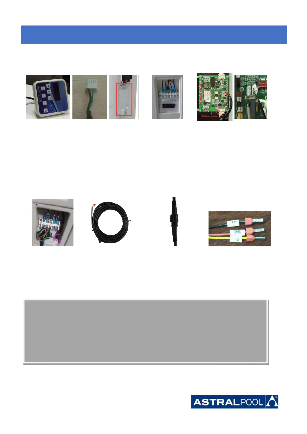
6.8 Installation of the Modbus/Fluidra Connect Signal Wire
Photo(6) Photo(7) Photo(8) Photo(9)
- Open the cover of the terminal box (photo6)
- Take the Modbus/Fluidra Connect signal wire from the accessories (photo7) and put the round end of the signal
wire into the signal wire from Modbus/Fluidra Connect Module. (photo 8)
- Three wire terminal :“A+” ,“B- ”, “GND” (Photo 9)
6.
6.
6.
Electrical
Electrical
Electrical
Wiring
Wiring
Wiring