What to do if Astralpool Heat Pump shows compressor 2 overcurrent protection?
- RRyan MooreSep 22, 2025
If your Astralpool Heat Pump displays a Compressor 2 overcurrent protection, it means that the compressor has an overcurrent. Check the system.
What to do if Astralpool Heat Pump shows compressor 2 overcurrent protection?
If your Astralpool Heat Pump displays a Compressor 2 overcurrent protection, it means that the compressor has an overcurrent. Check the system.
Why is there a large temperature difference between water-in and water-out in my Astralpool Heat Pump?
If the temperature differential between water-in and water-out is too large in your Astralpool Heat Pump, it may be caused by insufficient water flow or low water pressure. Check the water flow volume and inspect for any blockages in the water pipes.
What causes phase unbalance in Astralpool PROHEAT II?
A phase unbalance in your Astralpool Heat Pump is caused by a power failure. Check the electrical connections.
What to do if Astralpool Heat Pump displays high pressure malfunction of system 1?
If your Astralpool Heat Pump shows a high-pressure malfunction in system 1, it could be due to a gas charge that is too high or a possible system blockage. You should check the pressure switch and gas circuit, refrigerant circuit. Also, check for insufficient water flow and ensure the pump is running.
What causes the time limit running failure in Astralpool Heat Pump?
If your Astralpool Heat Pump displays the time limit running failure, it means that the running time has been exceeded. Check the time limit.
What to do if my Astralpool PROHEAT II has a signal failure?
If your Astralpool Heat Pump is showing a signal failure, the cable between the display and the card is badly connected. Check the continuity of the cable, and the terminal and the cables are well connected.
What to do if Astralpool PROHEAT II shows outdoor air temperature fault?
If your Astralpool Heat Pump displays an outdoor air temperature fault, it means the sensor is either open or short circuit. Check or change the sensor.
What to do if Astralpool Heat Pump shows low pressure transducer failure?
If your Astralpool Heat Pump displays a low-pressure transducer failure (Optional), it means the sensor is either open or short circuit. Check or change the sensor.
What to do if Astralpool PROHEAT II shows Cool1 sensor 1 failure?
If your Astralpool Heat Pump displays a Cool1 sensor 1 failure, it means the sensor is either open or short circuit. Check or change the sensor.
What causes fan overload protection in Astralpool PROHEAT II Heat Pump?
If your Astralpool Heat Pump indicates fan overload protection, it is due to fan overload. Check or change the fan motor.
Explains the meaning of information, warning, and forbidden symbols used in the manual.
Emphasizes careful reading for proper installation, start-up, and long-term performance.
Outlines the owner's legal liability for user safety and machine maintenance.
Addresses the mechanical refrigeration system and compliance with EU regulations on refrigerants.
Details essential personal protective equipment (PPE) for working with the equipment.
Identifies residual risks from assessment, detailing hazards like liquid accumulation, electrical shock, moving parts, and sharp edges.
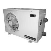
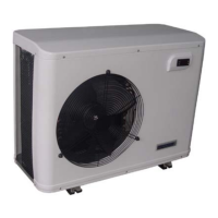
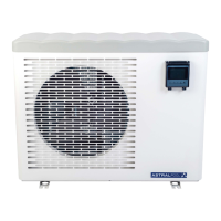
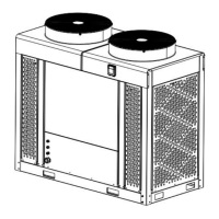
Lists and describes the main components of the heat pumps with a visual diagram.
Provides main technical data for standard, chiller, and indoor models, referencing tables.
Details electrical control panel components and main electrical data for the series.
Guides users to find electrical diagrams for different equipment models.
Directs users to image references for dimensional data and weight.
Reinforces PPE and safety training requirements for installation personnel.
Lists installation requirements like location, stability, orientation, and necessary clearances.
Specifies required water physical/chemical parameters and environmental limits for proper operation.
Explains the condensation drain mechanism and advises installing a siphon for odour prevention.
Lists and describes the primary functions of the NA8981 regulator, including display, defrost, and protections.
Details power supply and maximum output capacity for various components.
Explains how to access and modify controller parameters, including password protection.
Describes the basic operation modes (Cool, Heat, Auto, Manual) controlled by parameter F29.
Details how the machine operates in Cool, Heat, and Auto modes based on temperature setpoints.
Explains the start-up process and conditions for the Heat mode.
Explains the start-up process and conditions for the Cool mode.
Describes start-up and stop processes for Auto mode, including transitions between heating and cooling.
Explains how the controller manages defrosting based on evaporator temperature and time.
Explains how parameter F40 controls the water pump and its interaction with compressor operation.
Details fan speed control based on ambient temperature and parameter F27 settings.
Describes the operation of the unit when using a remote switch.
Covers various safety mechanisms that prevent damage or malfunction.
Explains the compressor delay time (F21) to prevent rapid ON/OFF cycles.
Describes phase connection errors and the resulting stop and error code A91.
Details over current protection, its trigger condition (F23), and associated error code A93.
Explains water flow monitoring and the error code A15 if flow is insufficient.
Describes high pressure switch operation, alarms, and blocking conditions.
Details low pressure switch operation, alarms, and blocking conditions, noting specific check periods.
Explains exhaust temperature monitoring, error codes A24/A25, and blocking conditions.
Covers protection against excessive water inlet/outlet temperature difference (F72), error A44.
Explains how low ambient temperatures (F26) restrict compressor start-up, allowing only electric heating.
Describes the antifreeze function, activating the water pump to prevent freezing in cold conditions.
Details how sensor failures are detected and handled, including auto-test and water pump behavior.
Provides a comprehensive list of error codes, their reasons, and recommended solutions.
Illustrates the LCD display layout and explains the meaning of various icons and indicators.
Explains how to use the display for functions like ON/OFF, setting temperature, and time.
Covers general terms of sale, warranty period, repair/replacement, and proof of purchase requirements.
Specifies warranty coverage for EU countries and the need to follow manufacturer instructions.
Outlines warranty limitations concerning consumer sales, wear and tear, and unauthorized handling.
Lists replacement parts for the housing of the heat pump units.
Provides codes and materials for replacement parts of the refrigerant circuit.
Lists replacement parts for the electrical circuit of the heat pump.
| Model | PROHEAT II Series |
|---|---|
| Type | Heat Pump |
| Max Water Temperature | 40°C |
| Heating Capacity | Varies by model |
| Power Supply | Varies by model |
| Noise Level | Varies by model |
| Dimensions | Varies by model (refer to specific model datasheet) |
| Weight | Varies by model (refer to specific model datasheet) |
| Water Flow Rate | Varies by model (refer to specific model datasheet) |






 Loading...