10
P1-8: Yellow: ANTI-LOCKING
This input is used to detect the presence of the key in the ignition switch in order to cancel locking of the doors
during an automatic rearming. In such cases, the alarm arms, but the doors are not locked. The same thing occurs
with an OEM alarm rearming, this wire will prevent locking.
Connect the YELLOW wire to the circuit (inside ignition switch harness - under steering column) that changes status
as soon as the key is inserted in the ignition switch ("Key reminder switch" - negative circuit only). For positive circuit,
use a relay to convert the signal to negative.
P2: INPUT/OUTPUT
P2-1 & 2: Red
THESE PINS ARE NOT FOR INSTALLATION USE. DO NOT CONNECT TO ANYTHING OR CUT FOR
ANY REASON!
P2-3: Black/Red: HOOD INPUT
Programmable N.O. or N.C. (Stage 1 – Level 3 on page 18) input allowing the module to detect the
hood being opened, preventing any remote start sequence to be engaged.
Run Black/Red wire into engine compartment through a rubber grommet. Cover wire with plastic loom and secure
with plastic ties, away from any heat source or sharp metal edges.
Install switch at the front of the engine compartment to ensure it activates the engine shut down feature when hood is
lifted up about 1.5 cm (1/2"). Use a 8mm (5/16") drill bit.
This circuit is a safety feature that must be connected.
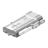
P2-4: White/Green: POSITIVE BRAKE SWITCH INPUT
Positive input used for programming and to neutralize a remote start sequence.
Connect White/Green wire to brake lights circuit at brake pedal switch (wire that provides +12 VDC only when brakes
are applied). Do not connect White/Green wire to cruise control cancel switch.
This circuit is a safety feature that must be connected.
P2-5: Orange/White: PARKING LIGHT / GLOW PLUG DETECTION INPUT (±)
Parking Light detection (Gas engine only):
This circuit can detect the parking Light left ON when the vehicle is parked and page the owner’s remote
(2 way remote only).
Locate the Parking light circuit of the car and hook it to that wire.
Program the polarity of the circuit at Stage 1 – Level 3 on page 18
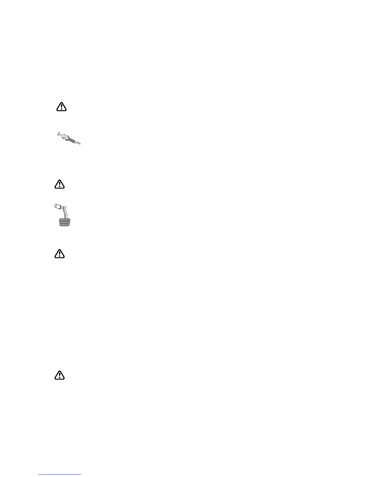
Glow Plug detection:
This circuit is used to delay starting of the vehicle until the preheating of the diesel engine has taken place.
Find the glow plug light circuit in the dashboard and connect this wire to that circuit. You will notice that some
glow plug light circuits in new diesel car/truck are now working in Data. In these cases, it is preferable to use
the glow plug wire on the engine or to program the unit to have a fix wait to start time. To do so, simply leave
this wire unconnected, program the Polarity to be “Negative” (Stage 1 – Level 3, page 18) and select the
desired wait time (15 seconds or 30 seconds) in that same Level.
This connection is optional, but is highly recommended for optimum starting.
The polarity of the glow plug circuit is determined by testing the circuit while the glow plug light is lit.