5
P2 CONNECTOR
PIN COLOR DESCRIPTION PURPOSE
6
Dark Green
Ground when running
Output (-) 150ma max
Connect this wire to a circuit that requires a ground during runtime.
Usually a transponder bypass interface.
See page 11 for more details about this output.
7
Orange
Anti-theft Output
(-) 150ma max
Connect this wire to an external starter-cut device or an extra anti-theft
status LED.
See page 11 for more details about this output.
Programming options are at Stage 1 – Level 4 on page 18.
8
Light Green
Horn Output
(-) 150ma max
Connect this wire to factory horn (-) circuit.
See page 11 for more details about this output.
Programming options are at Level 10 & 11 of the Stage 1, starting on page 20
and also at Stage 2 – Level 3 on page 23.
9
Red/
White
+12Volts Output
(+) 1amp max
Connect this wire to the positive side (coil) of additional relays.
Do NOT use for 2nd Ignition or 2nd Starter applications
See page 11 for more details about this output.
10
Black/
Green
Tachometer input
Connect this wire to a circuit in vehicle that provides a pulsed signal
(tachometer signal/RPM)
Default setting: 1 cyl. 800RPM.
See page 11 for more details about this Input.
Programming options are at Stage 1 – Level 2 on page 17.
11
Black Ground Input
Main Ground.
MUST be connected to left kick panel or firewall only.
12
N/C - Not used
13
Brown #1
14
White/
Blue
#2
15
White #3
16
Purple
Programmable Output
(-) 150ma max for each outputs
#4
Programmable outputs (-) used to control relays or low current circuit.
Programming options are in Level 5 (#1), Level 6 (#2), Level 7 (#3) and in Level
8 (#4) of the Stage 1, starting on page 19. A wiring example is shown page 12.
Programmable outputs default setting:
Output no 1: Pulse Before Start (Disarm)
Output no 2: Pulse After Shutdown (Rearm)
Output no 3: Trunk Release.
Output no 4: Dome Light.
Note concerning connector P16
When an AstroStart interface is connected into P16, verify if it requires the
programming of either one of the programmable outputs 1 & 2. If so,
consider using programmable outputs 3 & 4 instead (P2-15 & P2-16).
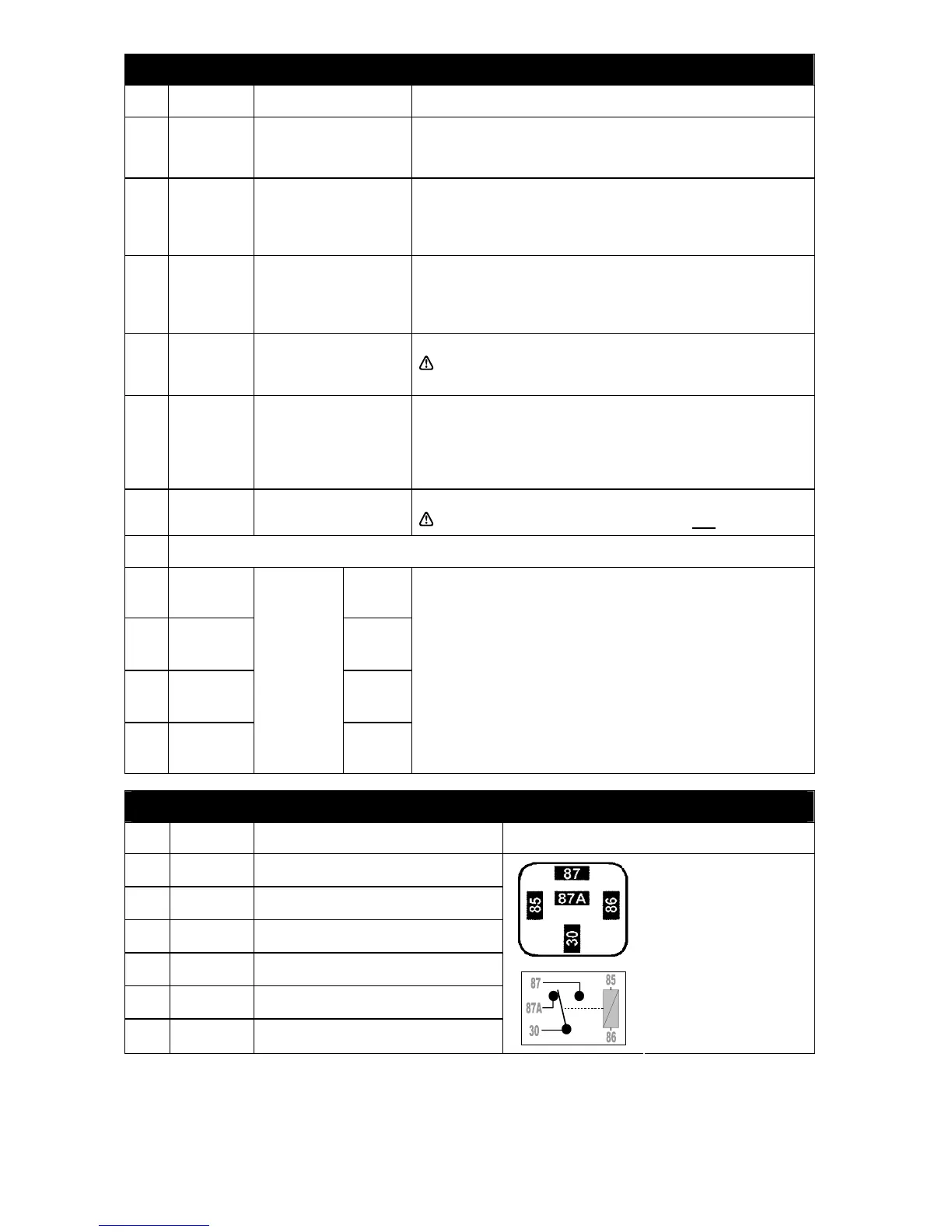
P3 CONNECTOR
PIN COLOR DESCRIPTION BUILT-IN RELAY DESCRIPTION
1
Brown LOCK Common - 30
2
White/Brown LOCK N.C. - 87A
3
Brown/White LOCK N.O. - 87
4
Blue UNLOCK Common - 30
5
White/Blue UNLOCK N.C. - 87A
6
Blue/White UNLOCK N.O. - 87
Contacts
85 and 86 are polarized
through the module internal
circuits.
Each relay is controlled by the
function "Locking" or
"Unlocking".
REMARKS: Connector P3 provides access to two on-board Bosch type relays to interface all types of power door
lock circuits. Refer to the AstroChart CD for door lock diagrams.