38 ASUS CUV4X-E User’s Manual
3. HARDWARE SETUP
Connectors
3. H/W SETUP
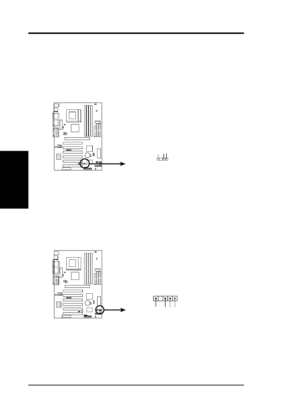
7) Chassis Intrusion Lead (4-1 pin CHASSIS)
This lead is for a chassis designed for chassis intrusion detection. This requires
an external detection mechanism such as a chassis intrusion monitor/sensor or
microswitch. When any chassis component is removed, the sensor is triggered
and a high-level signal is sent to this lead to record a chassis intrusion event.The
event is then be processed by software such as LDCM. When not using the
chassis intrusion lead, place a jumper cap over the pins to close the circuit.
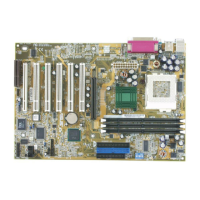
8) SMBus Connector (5-1 pin SMB)
This connector allows you to connect SMBus (System Management Bus) devices.
SMBus devices communicate by means of the SMBus with an SMBus host and/
or other SMBus devices. SMBus is a specific implementation of an I
2
C bus,
which is a multi-device bus; that is, multiple chips can be connected to the same
bus and each one can act as a master by initiating data transfer.
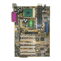
CUV4X-E
®
CUV4X-E Chassis Open Alarm Lead
CHASSIS
+5Volt
(Power Supply Stand By)
Ground
Chassis Signal
1
CUV4X-E SMBus Connector
CUV4X-E
®
SMBCLK
Ground
SMBDATA
+5V
1
SMB