ASUS IPILP-AR
12
6.2 Internal connectors
This section describes and illustrates the internal connectors on the motherboard.
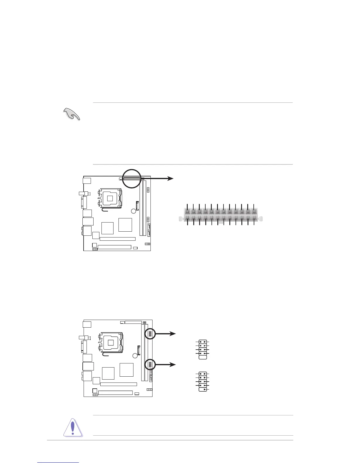
1. ATX Micro-Fit power connectors (24-pin ATXPWR1)
These connectors are for an ATX Micro-Fit power supply. The plugs from the
power supply are designed to t these connectors in only one orientation. Find the
proper orientation and push down rmly until the connectors completely t.
•
Make sure that your ATX 12V power supply can provide 8A on the +12V
lead and at least 1A on the +5-volt standby lead (+5VSB). The minimum
recommended wattage is 108W(only) for a fully congured system. The
system can become unstable and might experience difculty powering up if
the power supply is inadequate.
• You must install a PSU with a higher power rating if you intend to install
additional devices.
2. USB connectors (9-1 pin F_USB1/2)
These connectors are for USB 2.0 ports. Connect the USB/GAME module
cable to any of these connectors, then install the module to a slot opening at
the back of the system chassis. These USB connectors comply with USB 2.0
specication that supports up to 480 Mbps connection speed.
Never connect a 1394 cable to the USB connectors. Doing so will damage the
motherboard!