EasyManuals Logo

Asus P4P800 DELUXE User Manual

Asus P4P800 DELUXE
150 pages
To Next Page IconTo Next Page
To Previous Page IconTo Previous Page
Page #51 background imageLoading...
Page #51 background image
ASUS P4P800 Deluxe motherboard user guide
2-23
2.8 Connectors
This section describes and illustrates the internal connectors on the
motherboard.
1. Floppy disk drive connector (34-1 pin FLOPPY1)
This connector supports the provided floppy drive ribbon cable. After
connecting one end to the motherboard, connect the other end to the
floppy drive. (Pin 5 is removed to prevent incorrect insertion when
using ribbon cables with pin 5 plug).
P4P800
®
NOTE: Orient the red markings o
n
the floppy ribbon cable to PIN 1.
P4P800 Floppy Disk Drive Connector
PIN 1
FLOPPY1
Always connect ribbon cables with the colored to Pin 1 on the
connectors. Pin 1 is usually on the side closest to the power connector
on hard drives and CD-ROM drives, but may be on the opposite side
on floppy disk drives.

Table of Contents

Questions and Answers:

Question and Answer IconNeed help?

Do you have a question about the Asus P4P800 DELUXE and is the answer not in the manual?
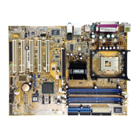
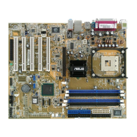
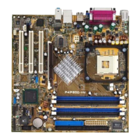
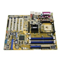
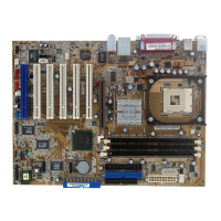
Asus P4P800 DELUXE Specifications

General IconGeneral
ChipsetIntel 865PE
SocketSocket 478
Form FactorATX
Memory TypeDDR
Memory Slots4
Max Memory4 GB
Expansion Slots1 x AGP 8X, 5 x PCI
Integrated LANYes
LAN Speed10/100/1000 Mbps
USB Ports8 x USB 2.0
Front Side Bus800/533/400 MHz
IDE2 x ATA 100
AudioADI AD1985 6-channel audio CODEC
RAID SupportYes
Storage Interfaces2 x ATA100, 2 x SATA150

Related product manuals