2. Serial ATA connectors (7-pin SATA1-4)
These connectors are for the Serial ATA signal cables for Serial ATA 3Gb/s hard disk
and optical disk drives. The Serial ATA 3Gb/s is backward compatible with Serial ATA
1.5Gb/s specication. The data transfer rate of the Serial ATA 3Gb/s is faster than the
standard parallel ATA with 133MB/s (Ultra DMA133).
Install the Windows
®
XP Service Pack 2 or later version before using Serial ATA.
GND
RSATA_TXP4
RSATA_TXN4
GND
RSATA_RXP4
RSATA_RXN4
GND
SATA4
GND
RSATA_TXP3
RSATA_TXN3
GND
RSATA_RXP3
RSATA_RXN3
GND
SATA3
GND
RSATA_TXP2
RSATA_TXN2
GND
RSATA_RXP2
RSATA_RXN2
GND
SATA2
GND
RSATA_TXP1
RSATA_TXN1
GND
RSATA_RXP1
RSATA_RXN1
GND
SATA1
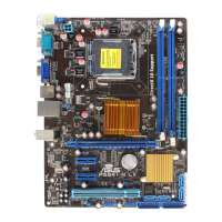
P5G41-M EVO
P5G41-M EVO SATA connectors
3. IDE connector (40-1 pin PRI_IDE)
The onboard IDE connector is for Ultra DMA 100/66/33 signal cable. There are
three connectors on each Ultra DMA 100 / 66 / 33 signal cable: blue, black, and gray.
Connect the blue connector to the motherboard’s IDE connector, then select one of the
following modes to congure your devices:
Drive jumper setting Mode of device(s) Cable connector
Single device Cable-Select or Master - Black
Two devices
Cable-Select
Master Black
Slave Gray
Master Master
Black or gray
Slave Slave
• Pin 20 on the IDE connector is removed to match the covered hole on the Ultra DMA
cable connector. This prevents incorrect insertion when you connect the IDE cable.
• Use the 80-conductor IDE cable for Ultra DMA 100/66/33 IDE devices.
If any device jumper is set as “Cable-Select”, ensure that all other device jumpers have the
same setting.
PRI_IDE
NOTE:Orient the red markings
on the IDE ribbon cable to PIN 1.
PIN1
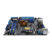
P5G41-M EVO
P5G41-M EVO IDE connector
1-12 Chapter 1: Product introduction
 Loading...