ASUS P7P55D-E LX
1-3
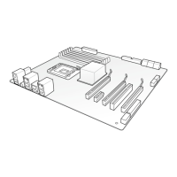
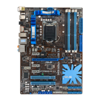
1.5.4 Layout contents
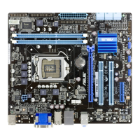
1.5.3 Motherboard layout
Ensure that you install the motherboard into the chassis in the correct orientation. The edge
with external ports goes to the rear part of the chassis.
Place this side towards
the rear of the chassis.
Connectors/Jumpers/Slots/LED Page Connectors/Jumpers/Slots/LED Page
1. LGA1156 CPU Socket 1-4
9. System panel connector (20-8 pin PANEL)
1-24
2.
ATX power connectors
(24-pin EATXPWR, 8-pin EATX12V)
1-22
10.
USB connectors (10-1 pin USB910,
USB1112, USB1314)
1-25
3.
DDR3 DIMM slots
1-9
11.
IO_LEVELUP switch 1-20
4.
CPU, chassis, and power fan connectors
(4-pin CPU_FAN, 4-pin CHA_FAN1,
3-pin CHA_FAN2, 3-pin PWR_FAN)
1-22
12.
Clear RTC RAM (3-pin CLRTC) 1-18
5.
MemOK! switch
1-19
13.
Front panel audio connector
(10-1 pin AAFP)
1-23
6.
JMicron
®
JMB361 IDE Connector
(40-1 pin PRI_IDE [Blue])
1-27
14.
Digital audio connector
(4-1 pin SPDIF_OUT)
1-26
7.
Intel
®
P55 Serial ATA connectors
(7-pin SATA 1-6)
1-23
15.
Standby power LED 1-28
8.
Marvell
®
Serial ATA 6.0 Gb/s connectors
(7-pin SATA_6G_1/2 [gray])
1-26 16. Serial port connector (10-1 pin COM1) 1-25