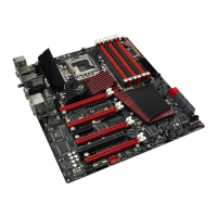
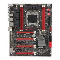
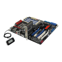
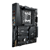
2.2.2 Layout contents
Refer to 2.9 Connectors for more information about rear panel connectors and
internal connectors.
Connectors/Jumpers/Switches/Slots Page
1. ATX power connectors
(24-pin EATXPWR, 8-pin EATX12V, 4-pin EZ_PLUG1—2)
2-45
2. Thermal sensor cable connectors (2-pin OPT_TEMP1–3) 2-43
3. CPU, chassis, and optional fan connectors (4-pin CPU_FAN;
4-pin PWR_FAN; 4-pin CHA_FAN1–3; 4-pin OPT_FAN1–3)
2-42
4. LGA1366 CPU Socket 2-9
5. DDR3 DIMM slots 2-14
6. LN2 Mode jumper (3-pin LN2) 2-31
7. Power-on switch 2-48
8. Reset switch 2-48
9. Q reset button 2-50
10. QPI_LL (3-pin QPI_LL_SW) 2-31
11. GO button 2-49
12. Marvell
®
Serial ATA 6.0 Gb/s connectors (7-pin SATA_6G_1/2 [red]) 2-39
13. ICH10R Serial ATA connectors (7-pin SATA 1-6 [grey]) 2-38
14. Clear RTC RAM (3-pin CLRTC_SW) 2-30
15. BIOS switch 2-49
16. System panel connector (20-8 pin PANEL) 2-46
17. USB connector (10-1 pin USB78, USB910, USB11) 2-40
18. OC Station connector (8-pin OC_STATION) 2-40
19. IEEE 1394a port connector (10-1 pin IE1394_2) 2-41
20. Digital audio connector (4-1 pin SPDIF_OUT) 2-43
21. Front panel audio connector (10-1 pin AAFP) 2-44
ROG Rampage III Formula 2-7
 Loading...