Do you have a question about the Asus ROG GR8 II Series and is the answer not in the manual?
Details the device's two SO-DIMM slots and maximum 32 GB memory capacity.
Highlights critical information on module compatibility, authorized technicians, and warranty details.
Steps 1-5: Power off, disconnect, position, remove screws, and detach the side cover.
Steps 6A-B: Release memory module by pressing clips and carefully removing it.
Steps 7-8B: Obtain replacement and install it into the slot, ensuring secure seating.
Steps 9-10: Re-attach the side cover and secure the top cover with screws.
Steps 1-2: Remove side cover, then remove HDD/SSD bracket screws.
Steps 3-6: Lift HDD/SSD assembly, disconnect SATA, remove bottom cover.
Steps 7-8: Remove rear panel cover and then remove support brackets A-C.
Steps 9-10: Disconnect power and PCIE cables from the motherboard.
Steps 11-13: Disconnect remaining cables and remove the motherboard.
Step 14: Flip motherboard and install the new memory module securely.
Step 15: Tilt motherboard and adjust rear I/O to fit chassis.
Steps 16-17: Push motherboard into chassis and secure with screws.
Steps 18-19: Reconnect power and PCIE cables to the motherboard.
Step 20: Reconnect WiFi antennas and cables to AAFP_F and FIO_USB3_34.
Step 21: Replace brackets A-C, ensuring cables are seated correctly.
Steps 22-23: Connect SATA cable and reinstall HDD/SSD assembly.
Steps 24-26: Replace rear panel, bottom cover, and top cover.
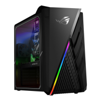
| Graphics | NVIDIA GeForce GTX 1060 |
|---|---|
| Weight | 4 kg |
| Processor | Intel Core i7-7700 |
| Memory | Up to 32 GB, DDR4 at 2400MHz |
| Operating System | Windows 10 Home |
| Networking | 802.11ac Wi-Fi, Bluetooth 4.2 |
| Front I/O Ports | 2 x USB 3.0, 1 x Headphone, 1 x Microphone |
| Rear I/O Ports | 1 x DisplayPort 1 x HDMI 1 x RJ45 LAN 1 x Optical S/PDIF out |
| Dimensions | 88 x 299 x 281.3 mm |





 Loading...