Do you have a question about the Asus ROG Strix G13CH and is the answer not in the manual?
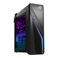
Visual identification of components and ports on the top of the chassis.
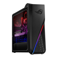
Detailed illustration of the rear panel connections and ports.
Details and images of the Video Graphics Array card component.
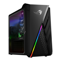
Visual identification of the system's main motherboard.
Illustrations and identification of DDR memory modules.
Visuals of various LED boards found on the bottom view of the chassis.
Identification of components located on the bottom side of the main board.
Image and identification of the power switch holder component.
Tools for screw removal and manipulation, including various screwdriver types and plastic blades.
Items for maintaining cleanliness and safety, such as alcohol wipes, gloves, and dust-free cloths.
Tools for securing components or manipulating small parts, like cable ties and needle-nose pliers.
Remove the specified screws to begin the slide door disassembly.
Gently pull the side doors to detach them from the chassis.
Attach the specified screws to secure components during assembly.
Mount the side door plate onto the chassis as per the diagram.
Complete the assembly by securing remaining screws.
Disconnect the yellow marked cables from the VGA card.
Open the computer case and remove the specified screws.
Press and unlock the VGA card mechanism for removal.
Take out the VGA card and its support bracket.
Attach the VGA bracket slot to the side of the VGA card.
Install stand-offs onto the motherboard for component placement.
Install the VGA card onto the motherboard using the designated screws.
Press down and unlock DDR modules before removing them from the slots.
Follow the specified order for installing DDR modules into the motherboard slots.
Release screws and disconnect the cable connector for the spring screw cooler.
Carefully take out the spring screw cooler assembly.
Disconnect the fan connector from the motherboard.
Remove the four screws securing the system fan.
Take out the 9cm system fan from the chassis.
Release the front bezel latch and disconnect its connectors.
Remove bezel screws and disconnect FFC cables.
Remove screws and detach the LED board.
Apply acetate fabric to the PIN HEADER and FPC connector for insulation.
Wind cables with acetate tape to enhance insulation layer and proper angle.
Remove two screws to detach the top cover.
Pull the latch to release and remove the top cover.
Disconnect the CPU fan connector from the motherboard.
Remove four screws securing the 12cm CPU fan.
Take out the 12cm CPU fan.
Remove four screws (red and green marks) from the front IO board.
Flip up the bracket, remove a screw, and separate the IO board.
Disconnect audio and USB 3.0 cables from the front IO board.
Assemble FIO bracket and small card with corresponding holes.
Mount stand-offs onto the motherboard for the new IO board.
Connect the necessary cables (power, USB, audio) to the new IO board.
Secure the USB 3.0 cable onto the motherboard.
Connect cables for the new front IO board to the motherboard.
Connect cables for the old front IO board to the motherboard.
Remove heatsink and SSD module for SSD1.
Remove heatsink, screw, and SSD module for SSD2.
Disconnect all marked cables from the main board.
Remove eight screws securing the main board.
Carefully lift and remove the main board from the chassis.
Release the CPU retention lever and remove the CPU.
Apply four sponges to the motherboard DIMM area as indicated.
Remove screws and shielding for the WLAN card.
Remove a screw, disconnect RF cables, and take out the WLAN card.
Push hooks to detach the power switch cable and holder.
Separate the power switch cable from its holder.
Remove four screws securing the HDD and IO shielding.
Disconnect the two connectors attached to the HDD.
Take out the HDD and its associated cable.
Press and push the IO shielding to remove it.
Cut the seven cable ties securing the power supply cables.
Remove four screws holding the power supply unit.
Disconnect the connector and take out the power supply.
Remove two screws and disconnect two cables for the side down LED board.
Remove three screws and disconnect one cable for side up/down LED boards.
Follow the images to properly tidy and route internal cables within the chassis.