30 ASUS TX97 User’s Manual
III. INSTALLATION
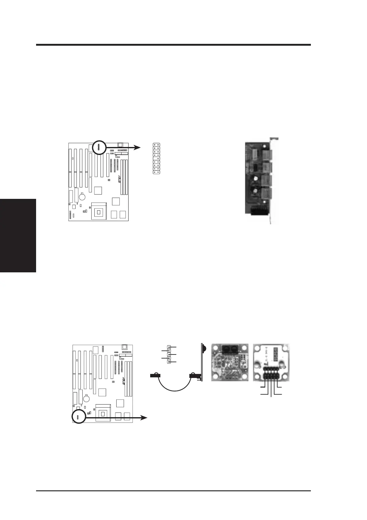
16. PS/2 Mouse, USB, Infrared Connector (18-pin block)
If you are using a PS/2 mouse, USB, or Infrared devices, you must purchase an
optional external connector set. The external connector set connects to the 18
pin block and mounts to an open slot on your computer's chssis. The system will
direct IRQ12 to the PS/2 mouse if one is detected. If not detected, expansion
cards can use IRQ12. See “PS/2 Mouse Control” in BIOS Features Setup and
“USB Funtion” in PnP and PCI Setup of the BIOS SOFTWARE. See “Second
Infrared” connector for details on the infrared connector.
PS/2 Mouse, USB, IrDA Module Connector
1
9
18
10
1: USB+5V
2: RUSB P0-
3: RUSB P0+
4: GND
5: F+5V
6:
RMSEECLK
7: GND
8: FIRRX
9: +5V
10: USB+5V
11: RUSBP1-
12: RUSBP1+
13: GND
14: (none)
15:
RMSEEDATA
16: GND
17: IRRX
18: IRTX
R
Optional USB/MIR
PS/2 Mouse
Infrared
USB 1
USB 2
17. Second Infrared (IrDA) & Fast IR-Compliant Infrared Connector (IR)
This is a second connector that supports the optional wireless transmitting and
receiving infrared module. This module mounts to a small opening on system
cases that support this feature. You must also configure the setting through
"UART2 Use Infrared" in Chipset Features Setup to select whether UART2 is
directed for use with COM2 or IrDA. Use the five pins as shown on the Back
View and connect a ribbon cable from the module to the motherboard according
to the pin definitions.
R
Infrared Module Connector
ront
ew
+5V
IRTX
IRRX
NC
GND
Back View
IRRX
+5V
IRTX
FIRRX
GND
For the infrared feature to be available,
you must connect an optional Infrared
module to the motherboard.
(Connectors)
III. INSTALLATION