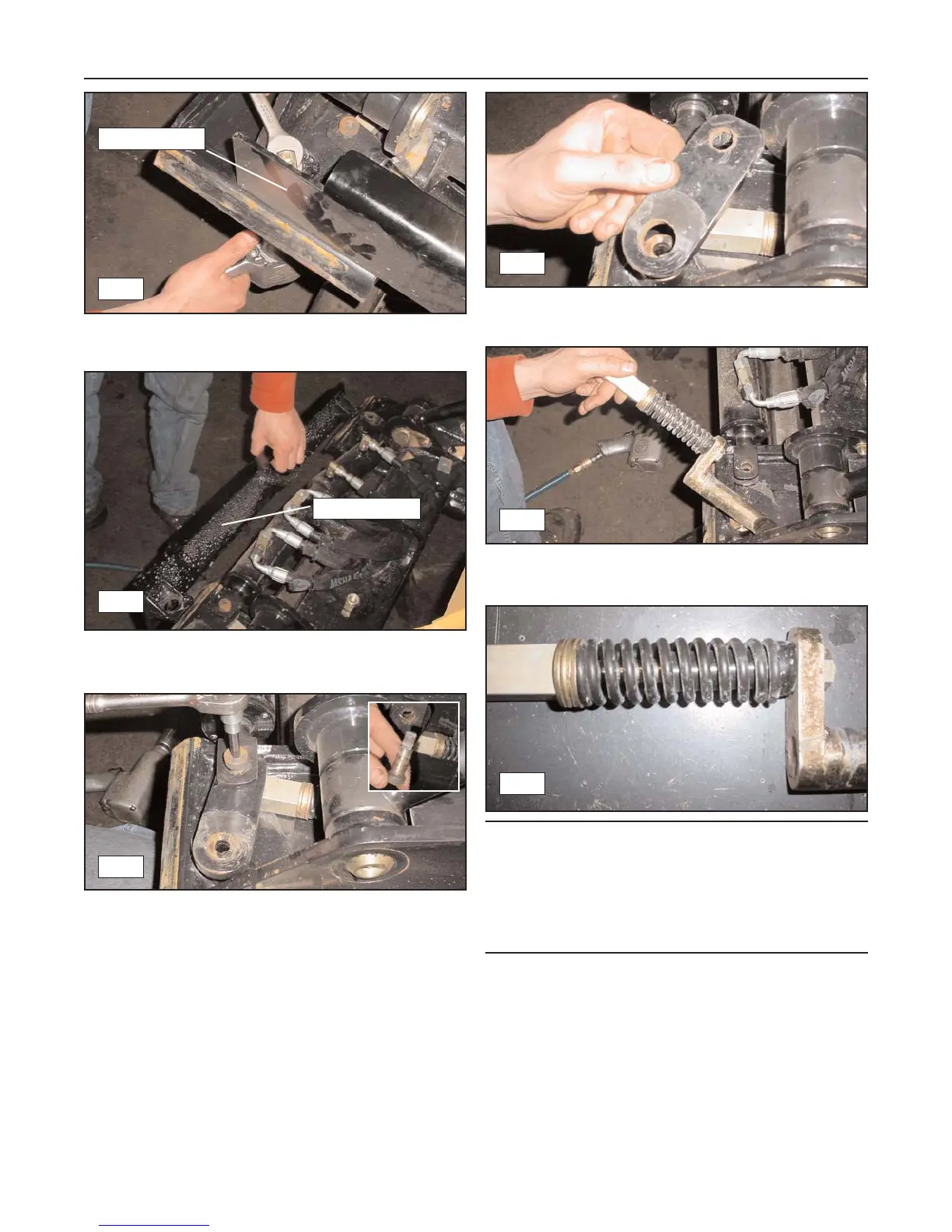
2. Remove the bolts (3) securing the upper guard to
the quick attach weldment. (fig. 15-2)
3. Remove the upper guard from the quick attach.
(fig. 15-3)
4. Remove the bolt securing the locking pin assembly
to the locking cylinder or latch handle. (fig. 15-4)
5. Remove the pivot link from the quick attach.
(fig. 15-5)
6. Slide the locking pin assembly out of the quick
attach. (fig. 15-6)
Note: At this time the locking pin assembly compo-
nents are easily accessible for replacement. Inspect
them for visible wear or damage and replace them as
necessary .
Pay attention to the quantity and position(s) of each
component to aid during reassembly. (fig. 15-7)
Installation
1. To install the quick attach locking pin assembly,
reverse the removal procedure.
15-2
Rubber Track Loader
15. Quick Attach
15-2
15-4
15-5
15-6
15-3
Upper guard
Upper guard
15-7
 Loading...