10 Instructions BS5 User Manual v2.0
Example GP1 Logger Program
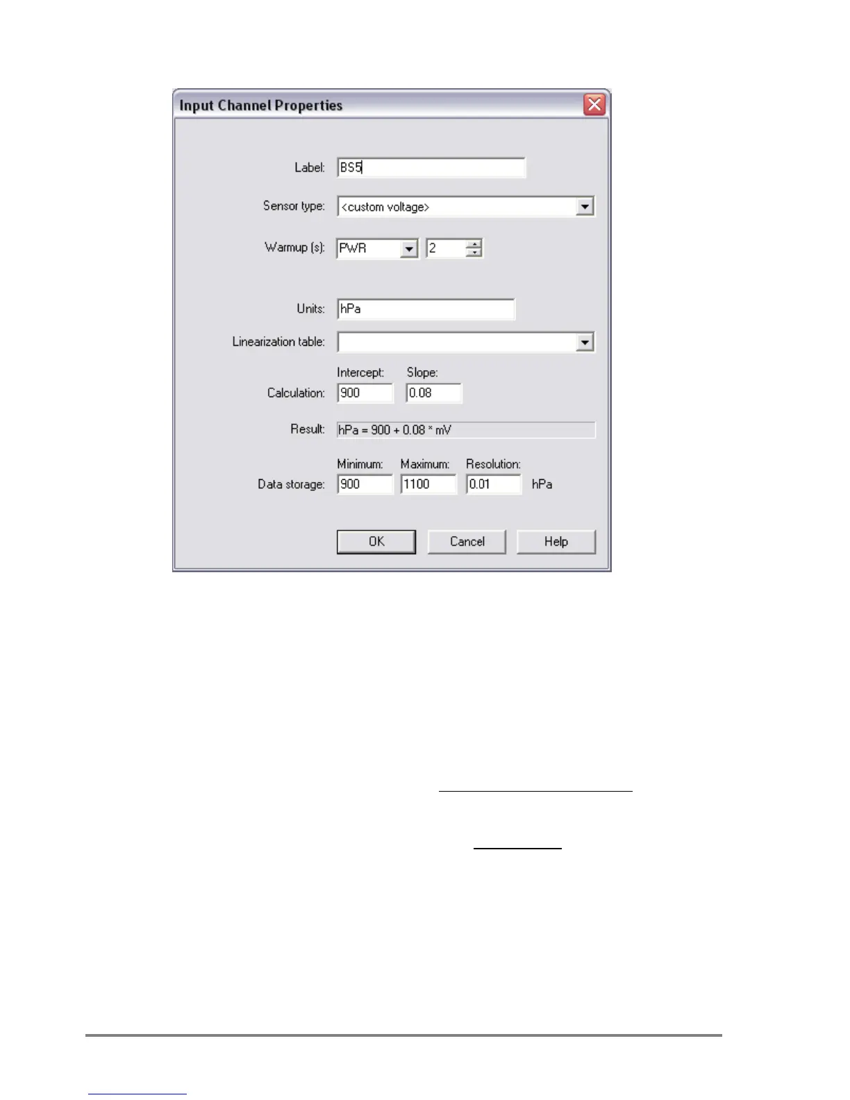
Figure 5. Channel Set-up for sensor range 900 to 1100 hPa
DeltaLINK 2.3 GP1 Program set up for a voltage channel
Sensor Type - custom voltage
Warm up - PWR 2 seconds
Units - hPa or mbars
Calculation - Intercept = Lower Limit
-
- Full scale Voltage is set via the SW1 DIP
switch on the BS5 sensor PCB and is in mV
Data storage - Minimum = Lower Limit
- Maximum = Upper Limit
- Resolution = 0.01