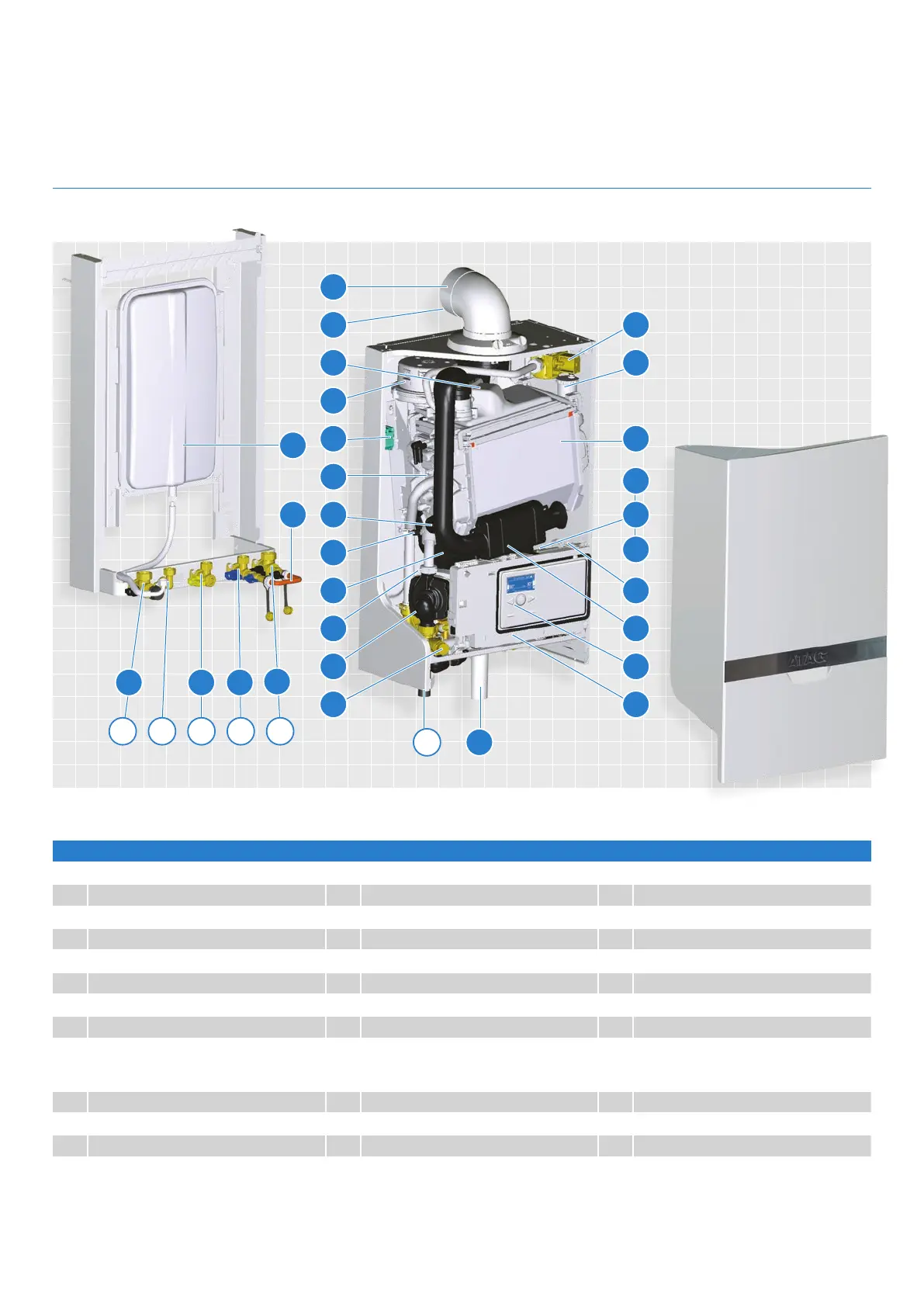
iC ECONOMISER PLUS COMBINATION BOILER LAYOUT
1 Heat exchanger 9 Control panel 17 Safety valve
2 Ignition unit 10 Three-way valve 18 DHW Economiser
3 Fan unit 11 Circulation pump 19 Siphon
4 Air supply damper 12 Filling loop 20 Isolation valve flow CH
5 Gas valve 13 Flue gas exhaust 21 Isolation valve gas
6 Automatic de-aerator 14 Combustion air supply 22 Isolation valve cold water
7 DHW plate heat exchanger 15 Boiler data plate 23 Isolation valve return CH
8 Control unit 16 Expansion vessel 24 Flue non return valve
T1 Flow sensor P1 Water pressure C Condensation pipe
T2 Return sensor G Gas pipe K Cold water pipe
T3 Hot water sensor A Flow pipe CH W Hot water pipe
F1 DHW flow sensor R Return pipe CH
Boiler layout
20
A W G
21
K
22
R
23
13
14 5
24 6
3
2 1
16
T1
P1
T2
18 15
7 4
11 9
12
817
19C
F1
T3
10
7
 Loading...


