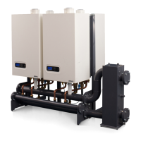
Installation & Servicing instructions ATAG XL
33
1. High voltage supply: 16 Connections
Position Connection Application
PG
Max.
V/A
1, 2, 3 Live Neutral Earth Power for boiler. Power cable not supplied 13,5* 230V
4, 5, 6 Live Neutral Earth Output 13,5
230V
4A
7, 8, 9 Live Neutral Earth System pump P3 13,5
10 Live Three-way valve CH (closed)
13,5
11 Live Three-way valve (open) or DHW pump P2
12 Neutral Three-way valve or DHW pump P2
13 Earth Three-way valve or DHW pump P2
14 Live DHW load pump P4
13,515 Neutral DHW load pump P4
16 Earth DHW load pump P4
2. High voltage switches: 6 Connections
Position Connection Application
PG
Max.
V/A
1, 2 1 2 Relay output fault signal 13,5
230V
5A
3, 4 3 4 Relay output heat demand 13,5
230V
5A
5, 6 5 6 Relay output external heat source / 2nd propane gas valve 13,5
230V
5A
3. Low voltage sensors: 14 Connections
Position Connection Application Tulles
1, 2 1 2 Hot water sensor T3 IP67
3, 4 3 4 Outdoor sensor T4 (advice) IP67
5, 6 5 6 CommonowsensorT10**(mustbeconnected) IP67
7, 8 7 8 On-Ocontact**/OpenThermcontact(autodetect) IP67
9, 10 9 10 0 -10 Volt input (temperature or load) IP67
11, 12 11 12 Blocking contact (bridge mounted) IP67
13, 14 13 14 LowwaterpressureswitchocontactNO(function not active) IP67
** If an outdoor sensor is NOT connected T-day is the maximum ow tempera-
ture. Go to Timeprog. options/timeprog. CH/T-day (see page 41-43)
* PG glands for cable duct already assembled in the factory. For a few connections, some
PG glands are supplied separately.
The maximum cable diameter for the terminals is 2.5mm
2
Connectthecablebypushingdownthecontrolontheterminalstripusingaatscrew-
driver(refertog.8.e).
4. Bus communication: 2-pole connector
Position Connection Application PG
Bus communication cable IP67
The AX00600U bus communication cable mutually connects the cascaded boilers by
4-pole connectors on the side of the connection terminals (2 boilers: 1 cable, 3 boilers:
2cablesetc.)andisttedwith2IP67tulles.Amaximumof8boilerscanbeconnected
by this cable.
0-10Volt
Open-
Therm
On/Off
T3
DHW
230V~
AC
230V
out
230V~
AC
230V
out
L
N
L
N
L
N
1 2 3 4 5 6 7 8 9 10 11 12 13 14 15 16
1 2 3 4 5 6
Error
signal
Heat
demand
signal
LPG
On/Off
1 2 3 4 5 6 7 8 9 10 11 12 13 14
T10
General
purpose
LWCO
NN
L
230V Pump / 3-WV.
L
230V Pump P3230V out230V~ AC
L
N
230V DHW pump
0-10Volt
Open-
Therm
On/Off
T3
DHW
230V~
AC
230V
out
230V~
AC
230V
out
L
N
L
N
L
N
1 2 3 4 5 6 7 8 9 10 11 12 13 14 15 16
1 2 3 4 5 6
Error
signal
Heat
demand
signal
LPG
On/Off
1 2 3 4 5 6 7 8 9 10 11 12 13 14
T10
General
purpose
LWCO
NN
L
230V Pump / 3-WV.
L
230V Pump P3230V out230V~ AC
T4
Out
8X.44.08.00 / 05.11
L
N
230V DHW pump
Bus
8X.44.09.00 / 05.11
0-10Volt
Open-
Therm
On/Off
T3
DHW
230V~
AC
230V
out
230V~
AC
230V
out
L
N
L
N
L
N
1 2 3 4 5 6 7 8 9 10 11 12 13 14 15 16 1 2 3 4 5 6
Error
signal
Heat
demand
signal
LPG
On/Off
1 2 3 4 5 6 7 8 9 10 11 12 13 14
T10
General
purpose
LWCO
NN
L
230V Pump / 3-WV.
L
230V Pump P3230V out230V~ AC
T4
Out
8X.44.08.00 / 05.11
L
N
230V DHW pump
Bus
8X.44.09.00 / 05.11
gure 8.b
gure 8.c
gure 8.d
gure 8.f
gure 8.e

 Loading...