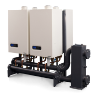
Installation & Servicing instructions ATAG XL
5
description components gure 1.a
1 heat exchanger 1 (All types OSS4)
2 heat exchanger 2 (XL110: OSS2, XL140:OSS4)
3 ignition unit
4 fan unit
5 damper
6 gas valve
7 automatic air vent
8 main switch 230V
9 boiler control unit
10 control unit MMI
11 connection terminal
12 connection terminal cascade bus communication
13 siphon
14 circulation pump
15 gas isolation valve (in optional boiler connections set)
16 servicevalvesow/return(inoptionalboilerconnectionsset)
17 llanddrainvalve(inoptionalboilerconnectionsset)
18 safety valve (in optional boiler connections set)
19 ueconnection(concentric)
20 airsupply(forparallelueconnection)
21 collectiveuepipe
22 information plate
T1 owsensor
T1a secondaryowsensor(onlyOSS4)
T2 return sensor
P1 water pressure sensor
G gas pipe
A owpipeCH
R return pipe CH
C condensate drain pipe
1
2
3
4
5
6
7
8
10
9
11
12
13
14
3
4
5
6
7
G C A
R
15 16
18
17
22
21
20 19
T1a
T2
P1
T1

 Loading...