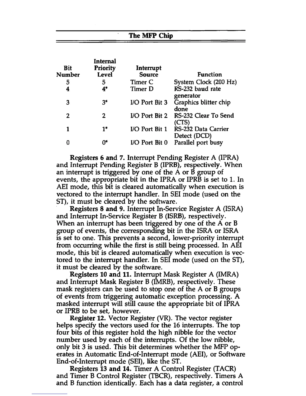
The MFP Chip
Bit
Internal
Priority Interrupt
Number
Level Source
Function
5 5
Timer C
System Clock (200 Hz)
4 4*
Timer D
RS-232 baud rate
3
3*
I/O Port Bit 3
generator
Graphics blitter chip
2 2
I/O Port Bit 2
done
RS-232 Clear To Send
1 1* I/O Port Bit 1
(CTS)
RS-232 Data Carrier
0
0*
I/O Port Bit 0
Detect (DCD)
Parallel port busy
Registers 6 and 7. Interrupt Pending Register A (IPRA)
and Interrupt Pending Register B (IPRB), respectively. When
an interrupt is triggered by one of the A or B group of
events, the appropriate bit in the IPRA or IPRB is set to 1. In
AEI mode, this bit is cleared automatically when execution is
vectored to the interrupt handler. In SEI mode (used on the
ST), it must be cleared by the software.
Registers 8 and 9. Interrupt In-Service Register A (ISRA)
and Interrupt In-Service Register B (ISRB), respectively.
When an interrupt has been triggered by one of the A or B
group of events, the corresponding bit in the ISRA or ISRA
is set to one. This prevents a second, lower-priority interrupt
from occurring while the first is still being processed. In AEI
mode, this bit is cleared automatically when execution is vec
tored to the interrupt handler. In SEI mode (used on the ST),
it must be cleared by the software.
Registers 10 and 11. Interrupt Mask Register A (IMRA)
and Interrupt Mask Register B (IMRB), respectively. These
mask registers can be used to stop one of the A or B groups
of events from triggering automatic exception processing. A
masked interrupt will still cause the appropriate bit of IPRA
or IPRB to be set, however.
Register 12. Vector Register (VR). The vector register
helps specify the vectors used for the 16 interrupts. The top
four bits of this register hold the high nibble for the vector
number used by each of the interrupts. Of the low nibble,
only bit 3 is used. This bit determines whether the MFP op
erates in Automatic End-of-Interrupt mode (AEI), or Software
End-of-Interrupt mode (SEI), like the ST.
Registers 13 and 14. Timer A Control Register (TACR)
and Timer B Control Register (TBCR), respectively. Timers A
and B function identically. Each has a data register, a control


 To Next Page
 Loading...