34
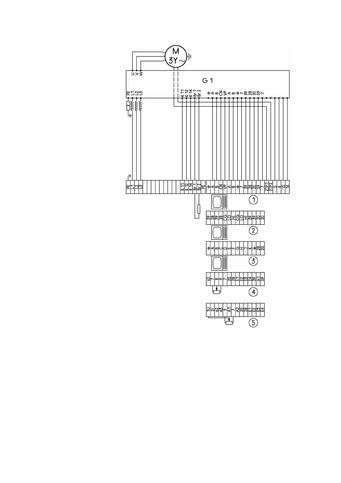
G1: Frequency converter
R: approx. 0Ω in TN and TT
network version
R = 10M Ω in IT network
version
L1, L2, L3: Power supply
input
K11, K12, K14: Converter
relay outputs
Br 1, Br 2: Brake rheostat
2TP1, 2TP2:
PTC connection
5, 6, 15, 16: Keypad
connection (parameter
setting)
c PROFIBUS-DP at choice
d Systembus (CAN) at
choice
e Interbus at choice
f Standard I/O at choice
g Applications I/O at choice
Figure 11:
Overview circuit diagram of the compact drive
without relay and PTC tripping device for all
network versions.
For details, see the converter installation instructions
and the circuit diagram for functional unit 1-5