ATG429EBPOperationManual
2‐2
June4,2015
Rev.A2
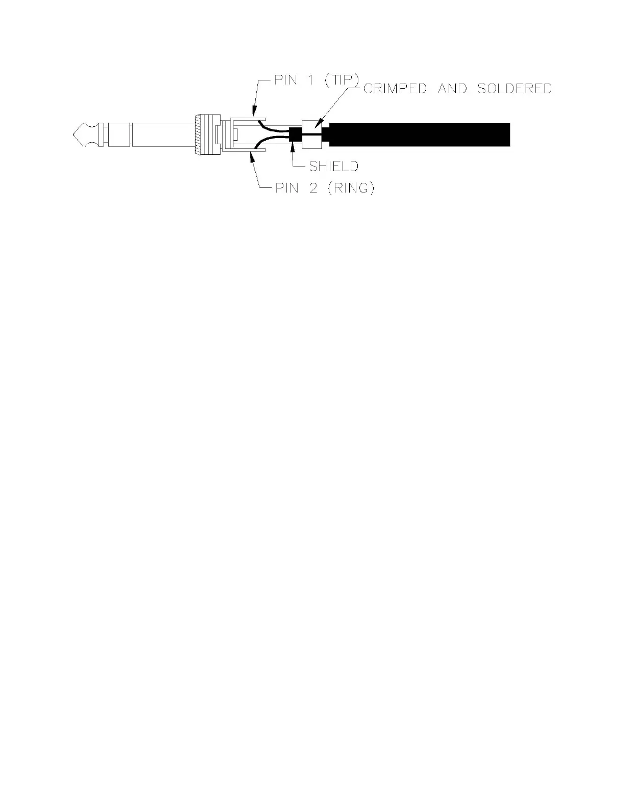
Figure 2-2. Phone Plug Termination
2.4 POST INSTALLATION CHECK
2.4.1 UNIT SELF TEST
The 429EBP performs a self test routine on initial power up. The following tests are performed:
1. The message EBP VERSION *.* is displayed. (*.* = software revision). Red LED's on the
front of the unit will be lit for approximately 0.5 seconds each in the following order: EVEN
and ODD Parity, TX and RX. For the remainder of the self test, unless an error condition
exists, the LED's are extinguished. If one of the LED's fails to light, the unit should still
function properly, but the LED should be replaced at the earliest opportunity. If all LED's fail
to illuminate and the display is blank or display's random data, then a catastrophic unit failure
has occurred or the batteries are completely discharged.
2.
The EPROM is checked by summing all the memory locations and comparing the result to
the known checksum. If the checksums do not match, the unit will signal a checksum error by
flashing the RX LED and will attempt to write "CHECKSUM ERROR" to the display. (If the
entire EPROM has failed, however, or if one of the locations in the checksum subroutine is
bad, the program will not be able to execute properly.)
3.
The 429EBP has RAM in two independent IC's. The unit tests each RAM section separately
for data retention and address integrity. It begins by writing the lower 8 bits of the location
address to the location. It completely writes all locations of the section. It will then read each
location and check its value. If all is OK, it will repeat this sequence with the exception that it
will write the complement of the lower 8 bits of the location address to the location. It
performs this sequence for each RAM section.
If the first IC fails this test, the unit will flash the EVEN parity LED and attempt to write "NSC
RAM ERR" to the display. This indicates that U5 has failed its test. If the second IC fails this
test, the unit will flash the ODD parity LED and will attempt to write "MAIN RAM ERR" to the
display. This indicates that U3 has failed its test. The unit will then loop indefinitely reading
from the failed location.
4.
The 429EBP has a loop back feature on the digital board to completely test the digital portion
of the transmit and receive circuitry. The unit will turn on the loop back circuitry and transmit a
word with a label of 0 and a data pattern of AA55AA. After a brief pause, the unit will read it's
receive buffer and check the data against the transmitted data. If the data is not what is
expected, the unit will flash the TX LED and attempt to write "LOOP BACK FAILED" to the
display. No further operations will be possible until the cause of the failure is corrected.
The Loop test and Ram tests are not performed if the unit Trap mode is active.
If all tests have been successfully completed, the unit will display "SELF TEST OK" for approximately 2
seconds and will then enter the operational receive mode and display the number of different labels
currently being received (or number of words in the trap buffer if TRAP mode is active).