5
Wiring
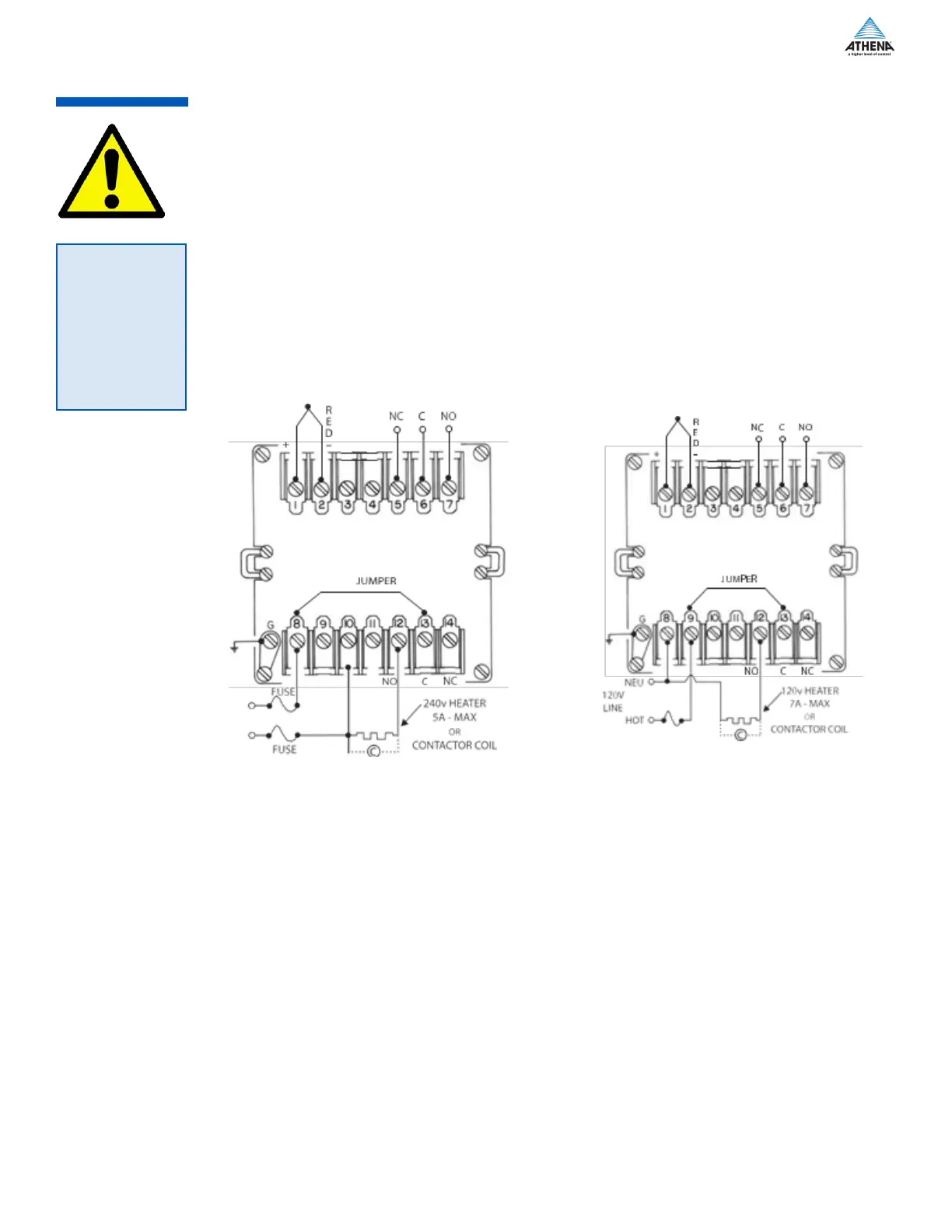
Figure 2a. Typical 240 Vac for -B & -T Output
Typical Wiring Diagrams for -T & -B Outputs
B-Type -
840 W maximum. 120 Vac heater. (Non-inductive loads only) For larger loads, replace heater connections
with contactor, as required. Maximum inductive load rating is 3 A at 120 V and 1.5 A at 240 V. The N.C. con-
tacts can be used for cooling.
T-Type -
solid state relay with SPST contacts. The -T units can handle contactors or resistive loads up to 1 A with 10 A
inrush maximum. For -T units use a 1 A, 250 V fast blow fuse.
-L Output (Limit Controller)
Wiring can be similar to that shown for “B.” The controller’s relay is de-energized until the reset button on the
front panel is momentarily pressed. The relay will energize if the sensor temperature is below setpoint. The
common and N.C. terminals can be used to indicate alarm condition remotely when wired to lights, bell, etc
Thermocouple AlArm conTAcTs (opTionAl)
Figure 2b. Typical 120 Vac for -B & -T Output
Thermocouple
AlArm conTAcTs
(opTionAl)
 Loading...