4
Mounting
Measurements
between centerlines
of panel cutouts
are the minimum
recommended.
Power Wiring
Circuits
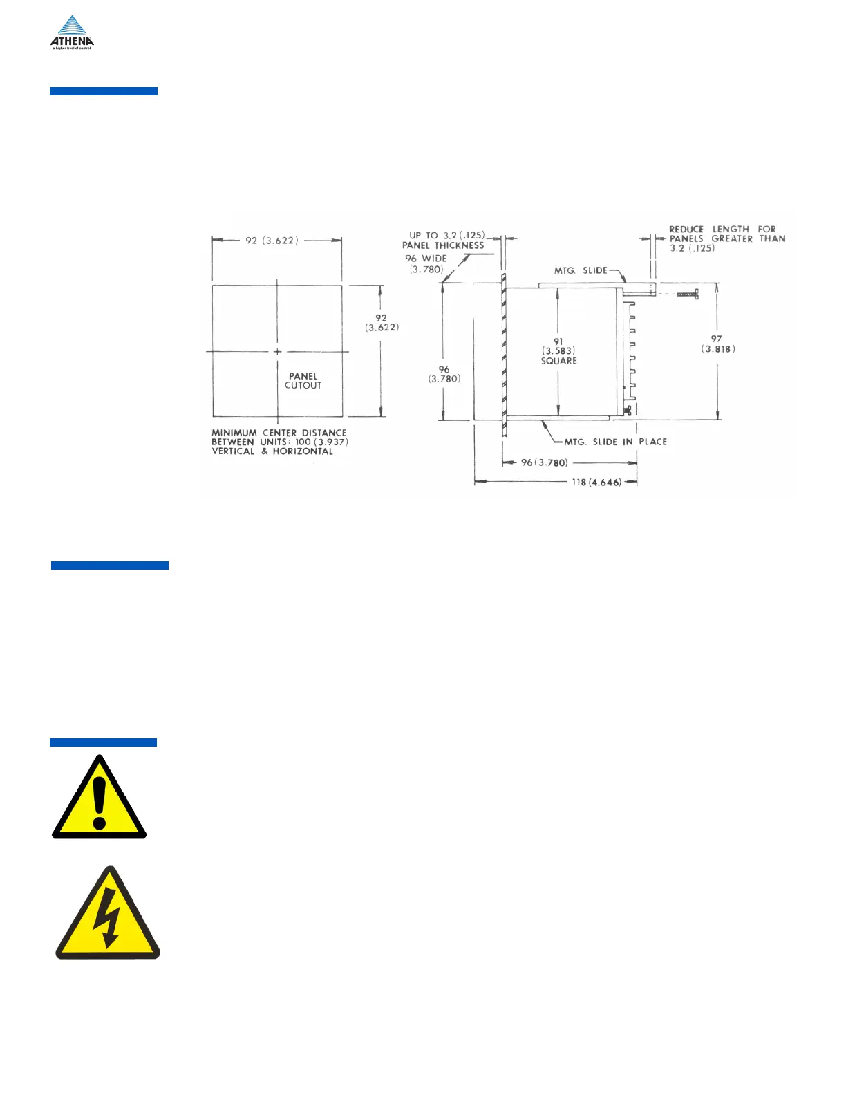
Mount controller into 92 mm (3-5/8”) square cutout (1/4-DIN). See Figure 1 for cutout and case dimensions.
The plug-in controller does not have to be removed from its housing for mounting.
Remove the two screws in the back of the case that hold the mounting slides, and then remove the slides.
Insert case from front of panel and reinstall the two slides and two screws. The length of the slides must be
reduced if the controller is to be mounted in an extra thick panel. If the controller has been unplugged from
its housing, the top of the housing can be determined by the serial number tag.
Consult serial tag on the unit and select power wiring diagram for the model specified. All wires are connect-
ed to the terminals on the back of the case. Screw terminals are provided. Make appropriate connections
using proper size wire for rated controller load power circuits. (On -B output model, use AWG #14 wire; for
-F, -S and -T outputs use #14, 16, or 18 wire.) The unit can be supplied with 120 V or 240 Vac, 50/60 Hz.
Select proper terminal for the voltage used.
IMPORTANT: All electrical wiring connections should be made only by trained personnel, and in strict
accordance with the National Electrical Code and local regulations.
The Series 2000 controller has built-in circuitry to reduce the effects of electrical noise (RFI) from various
sources. However, power and signal wires should always be kept separate. We recommend separating
connecting wires into bundles: power; signal; alarms; and outputs. These bundles should then be routed
through individual conduits. Shielded sensor cables should always be terminated at one end only.
If additional RFI attenuation is required, noise suppression devices such as an R.C. snubber at the external
noise source may be used. If you wish, you may order this suppressor directly from Athena, part number
235Z005U01.
Figure 1: Cutout and case dimensions
Type “B” Relay with 7 A at 120 V and 5 A at 240 V contacts, on-o and time proportioning
Type “F” Signal current, 4-20 mAdc
Type “L” Relay with 7 A at 120 V and 5 A at 240 V contacts, on-o, reset switch
Type “T” Solid state relay 1 A, 120/240 V resistive load; 1 A, 120/240 V, 10 A inrush, inductive load
(not U.L. rated)
Type “S” Pulsed 20 Vdc, for driving solid state relays
Output
Configurations
 Loading...