6
Wiring
-F, -S Output - 120/240 Vac
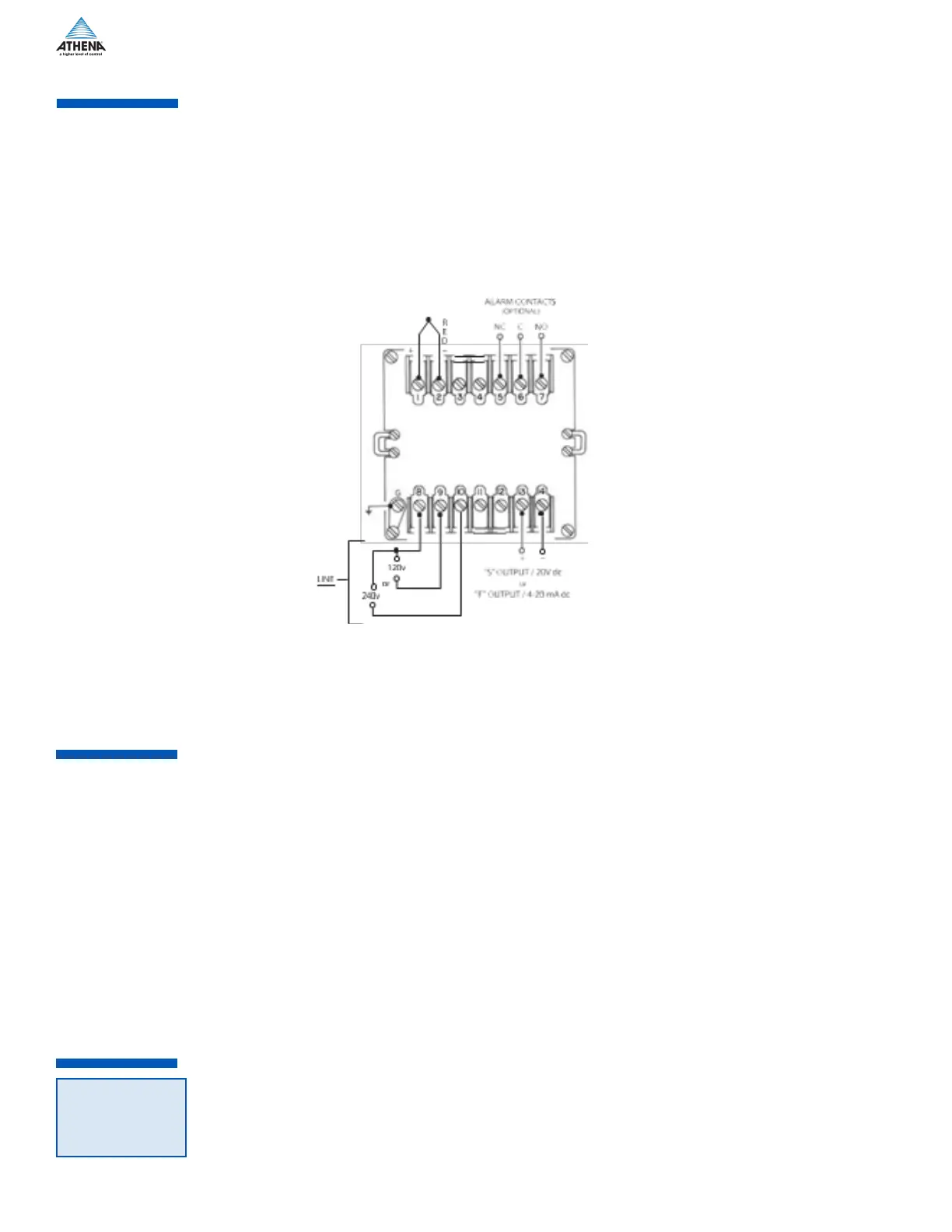
The -F output is 20 mA at the low temperature end of the proportional band and 4 mA at the upper end of
the proportional band. Maximum load resistance is 1000 ohms.
The -S output is a time-proportioned 20 Vdc signal. These controllers cannot be used with a device that
does not have an isolated input. An ungrounded thermocouple must be used if there is ac leakage or a
ground in the input of the device connected to the controller’s output.
Thermocouple
Wiring
Circuits
Use thermocouple and extension wire that conforms to the appropriate thermocouple type specified on the
serial number tag. In thermocouple circuits, the negative lead is colored red. Extension wires must be of suf-
ficient size so that on long runs the thermocouple circuit resistance does not exceed 100 ohms.
Do not run thermocouple leads in the same conduit as the power lines. If shielded thermocouple wire is
used, terminate the shield only at the controller end using the corner screw provided for that purpose.
Standard Thermocouples
I.S.A. Type Materials Color Code (U.S.A.)
J Iron-Constantan (I/C) White (+)/Red(-)
K Chromel-Alumel (C/A) Yellow (+)/Red (-)
T Copper-Constantan Blue (+)/Red (-)
Figure 3: Typical 120/240 Vac for -F & -S Output
Thermocouple
AlArm conTAcTs
(opTionAl)
RTD Wiring
Circuits
The 2002 units are designed for 100 ohm platinum RTDs. Two-wire RTDs are connected to terminals -1
and -2 with a jumper connecting 2 to 3. Keep leads short and use heavy gauge copper extension wires if
necessary, to minimize lead resistance. For long runs 3-wire RTD should be used and wire gauge should be
sufficient that resistance does not exceed 10 ohms.
DO NOT RUN RTD LEADS IN THE SAME CONDUIT AS POWER LINES.
If shielded RTD wire is used, terminate the shield only at the controller end, using the corner screw provided
for that purpose.
NOTE:
 Loading...