8
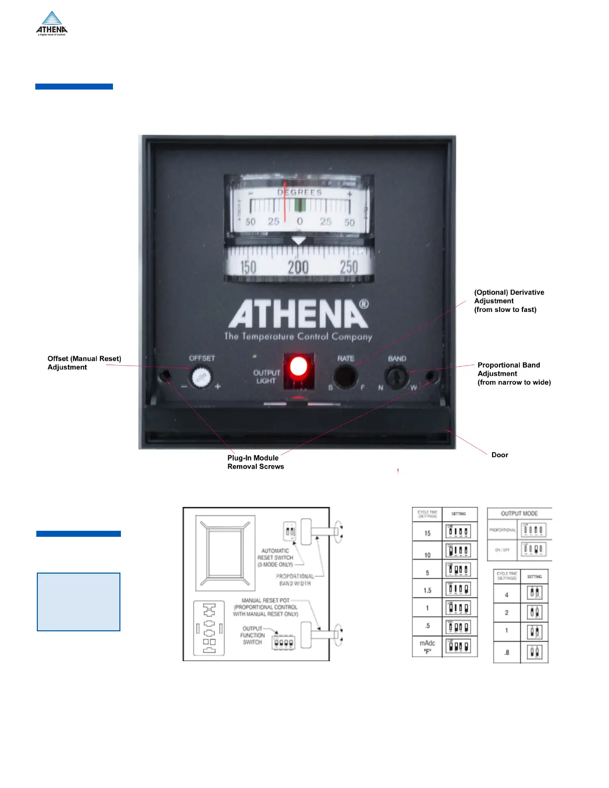
Layout of the front panel is shown below. To reach the adjustments, swing the top of the door forward and
down. The proportional band adjustment is on the right side and sets the gain of the controller. The offset
(manual reset) adjustment is on the left and corrects for offsets from the setpoint temperature. The output
indication (LED) can be seen through a window in the door.
Units ordered with Option A (3-Mode PID) will not have a manual reset adjustment. Instead, these units
have an automatic rate adjustment on the front panel and an automatic reset selector switch inside the unit.
Front Panel
Layout
Figure 5a. Bottom board illustration
Figure 5b: Output Function Switch Chart
NOTE:
Output Function
Switches
—Switch No. 4 in “ON” position is for “B” or “T” outputs when driving mechanical devices such as
contactors.
—Switch No. 4 in “OFF” position is for “T”, “F”, or “S” outputs when driving devices that can withstand rapid
cycling, such as solid state devices , solenoids, etc.
Figure 4. 2000 shown with open door
 Loading...