2
Sensor Input
Connections
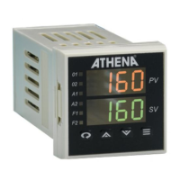
Figure 5. Thermocouple Input Wiring
Make sure that you are using the
appropriate thermocouple and
extension wire. Connect the neg-
ative lead (generally colored red
in ISA-type thermocouples) to
contact #9; connect the positive
lead to contact #10. Extension wires must be the same
polarity as the thermocouple.
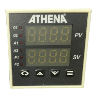
Figure 6. RTD Wiring
The Series 16 accepts input
from 2- or 3-wire, 100 ohm
platinum resistance tempera-
ture detectors (RTDs). Connect
2-wire RTDs to contacts #9 and
#10, with a jumper across
contacts #8 and #9. Keep
leads short and use heavy
gauge copper extension wire, if necessary, to minimize lead
resistance. For long runs, 3-wire RTDs should be used.
Thermocouple circuit
resistance should not
exceed 100 ohms for
rated accuracy; errors
will occur at higher
resistance values. If
shielded thermocouple
wire is used, terminate
the shield only at panel
ground.
Use wire with a
resistance no greater
than 10 ohms. An error
of 0.2° F will result for
each additional 10
ohms of resistance
encountered. If
shielded RTD wire is
used, terminate the
shield only at panel
ground.
Note: For 2 Wire RTD
Jumper 8 & 9
 Loading...