ATI Q46D Dissolved Oxygen System Part 4 – Electrical Installation
16
O&M Manual
Rev-N (4/21)
The analog outputs from the system are present at terminals TB1 and TB2. The loop-load
limitation in this configuration is 450 Ohms maximum for output 1 and 1000 ohms maximum for
output 2. Also note that these two outputs are completely isolated from each other to ensure that
ground loops do not result from the connection of both outputs to the same device such as a PLC
or DCS.
A ribbon cable connects the power supply assembly with the microprocessor assembly located in
the front section of the enclosure. This cable may be unplugged from the front section of the
monitor if service is needed but should normally be left in place during installation.
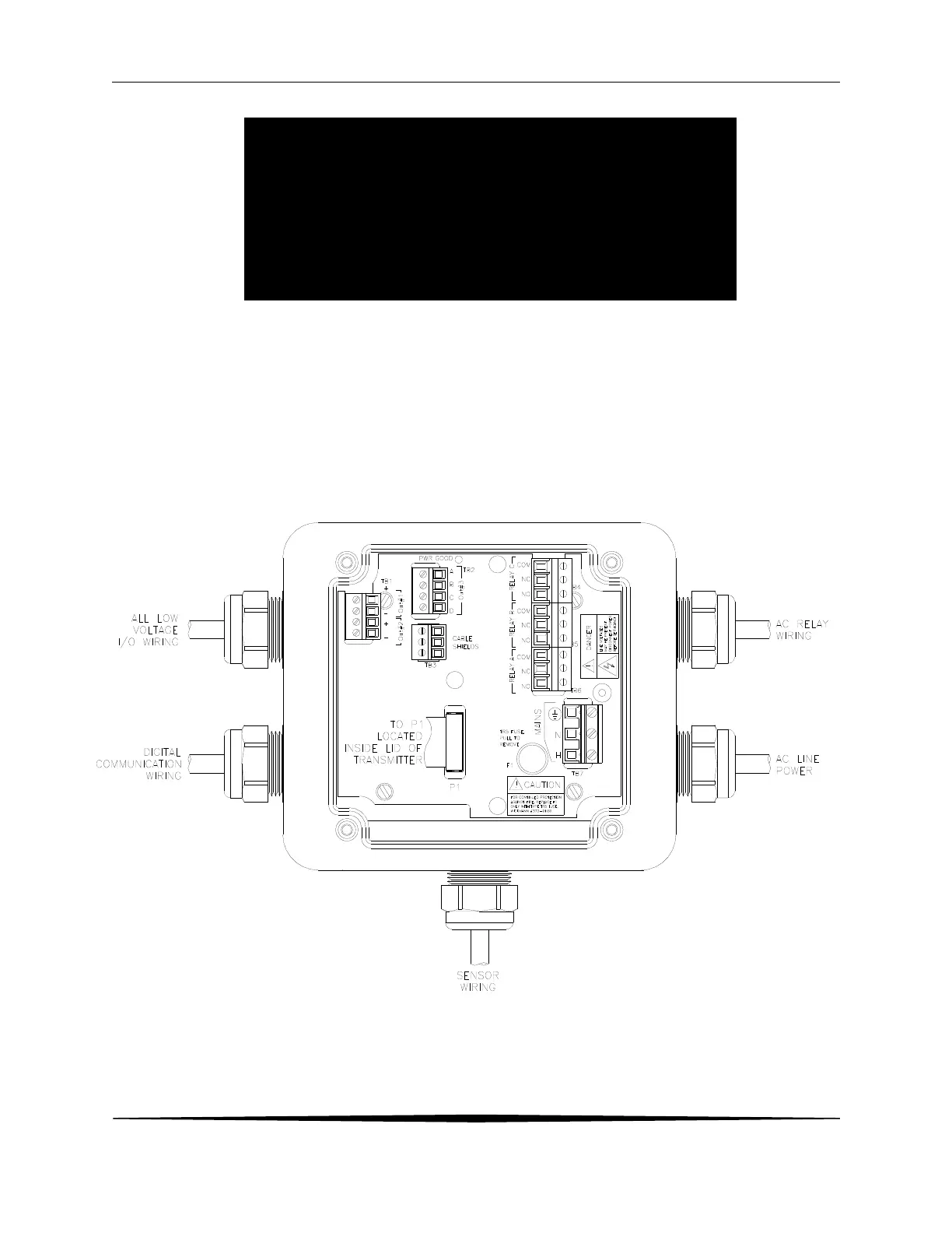
Figure 9 - AC Power Connections
The power strip, TB5, allows up to 12 AWG wire. A wire gauge of 16 AWG is recommended to allow for
an easy pass-through into the M16 ports when wiring.
WARNING
Disconnect line power voltage BEFORE connecting line power
wires to Terminal TB5 of the power supply. The power supply
accepts only standard three-wire single phase power. The power
supply is configured for 115 VAC or 230 VAC operation at the
factory at time of order, and the power supply is labeled as such.
Do NOT connect voltages other than the labeled requirement to
the input.
 Loading...