Do you have a question about the Atlantic alfea excellia duo 11 and is the answer not in the manual?
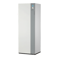
Details the components included in the product packaging.
Explains key terms used in the manual for clarity.
Lists the technical data and performance characteristics of the unit.
Outlines the intended uses and capabilities of the heat pump.
Outlines essential regulations for installation and maintenance.
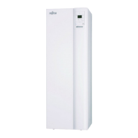
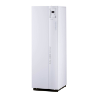
Provides guidance on checking the unit upon receipt and handling it.
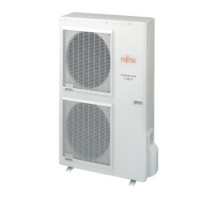
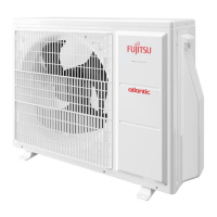
Offers advice on safely moving and positioning the outdoor unit.
Emphasizes the importance of preventing contamination in refrigerant circuits.
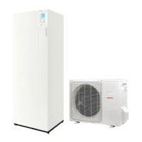
Lists the accessories included with the outdoor and hydraulic units.
Guides the choice of optimal location for the outdoor and hydraulic units.
Covers the installation process and requirements for the outdoor unit.
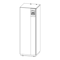
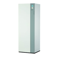
Provides guidance for the safe and correct installation of the hydraulic unit.
Details the procedures and precautions for making refrigeration connections.
Explains the critical steps for filling the system with refrigerant gas.
Describes the initial test to ensure the integrity of the refrigeration circuit.
Details the process of creating a vacuum and introducing refrigerant.
Explains how to perform a leak test on the refrigeration circuit.
Explains when and how to add extra refrigerant based on connection length.
Provides instructions for collecting refrigerant in the outdoor unit.
Covers general trade practices and regulations for hydraulic connections.
Details the procedure for connecting the domestic hot water circuit.
Explains the process of flushing the heating system before filling.
Guides on filling the system with water and removing air.
Details connections for fan convectors or dynamic radiators.
Describes the installation of thermal insulation on fittings to prevent condensation.
Explains how to adjust heating circulation pump speeds.
Provides comprehensive guidance on all electrical connections for the unit.
Guides the electrical connections for the single-phase outdoor unit.
Guides the electrical connections for the three-phase outdoor unit.
Details electrical connections for the hydraulic unit.
Provides guidelines for installing the outdoor sensor for accurate temperature readings.
Covers installation and configuration of room thermostats and control units.
Outlines the steps for the initial start-up and configuration of the unit.
Explains how to configure the room thermostat for heating zones.
Details the configuration process for room control units.
Describes the components of the user interface and control options.
Explains the functions and definitions related to the unit's controls.
Details the symbols and information shown on the unit's display.
Explains how the heat pump regulates water temperature based on outdoor conditions.
Guides on parameterizing temperature control based on emitters and insulation.
Explains how the heat pump regulates water temperature based on outdoor conditions.
Explains parameter 720 for adjusting heating curve based on outdoor temperature.
Explains parameter 721 for adjusting the initial temperature offset.
Provides actions to take for heating discomfort based on sensations.
Guides on how to parameterize the unit's settings.
Details various function lines for settings, diagnosis, and status.
Describes programming for a second heating circuit.
Covers programming for domestic hot water production times.
Details programming for cooling operation.
Explains holiday program settings for heating circuit 1.
Explains holiday program settings for heating circuit 2.
Settings for adjusting heating circuit 1 parameters.
Setting the desired comfort temperature for heating.
Setting a lower temperature for reduced heating periods.
Setting the temperature to prevent frost.
Defining the maximum comfort temperature.
Adjusting the heating curve slope.
Adjusting the heating curve offset.
Setting limits for summer and winter heating modes.
Minimum flow temperature setting.
Maximum flow temperature setting.
Adjusting room thermostat influence on settings.
Limiting room temperature adjustments.
Setting a quick reduction in temperature.
Maximum time for optimum start control.
Maximum time for optimum stop control.
Settings for adjusting heating circuit 1 parameters.
Start range for increasing the reduced setpoint.
End range for increasing the reduced setpoint.
Setting for mixer valve boost function.
Setting the running time for actuators.
Function for drying concrete slabs with temperature programming.
Settings for cooling circuit 1.
Setting the operating mode for cooling.
Setting the desired comfort temperature for cooling.
Controlling release of cooling based on time programs.
Flow temperature setpoint at 25°C outdoor temperature.
Flow temperature setpoint at 35°C outdoor temperature.
Setting the cooling limit based on outdoor temperature.
Time lock after heating ends.
Summer compressor start temperature.
Summer compressor end temperature.
Increase in summer compressor setpoint.
Minimum flow temp at 25°C outdoor temp.
Minimum flow temp at 35°C outdoor temp.
Adjusting room influence on cooling settings.
Limiting room temperature in cooling mode.
Decreasing the mixer valve in cooling mode.
Running time for actuators in cooling.
Mixer valve operation in heating mode.
Time lock for dewpoint limiter.
Settings for primary control and system pump.
Changing operating mode between heating and cooling.
Settings for adjusting heating circuit 2 parameters.
Setting comfort temperature for the second heating circuit.
Setting reduced temperature for the second heating circuit.
Setting frost protection temperature for the second heating circuit.
Defining maximum comfort temperature for the second heating circuit.
Adjusting heating curve slope for the second circuit.
Adjusting heating curve offset for the second circuit.
Setting limits for summer/winter heating on the second circuit.
Settings for adjusting heating circuit 2 parameters.
Maximum flow temperature setting for the second heating circuit.
Adjusting room influence for the second heating circuit.
Limiting room temperature for the second heating circuit.
Setting quick setback for the second heating circuit.
Maximum time for optimum start control for the second circuit.
Maximum time for optimum stop control for the second circuit.
Start range for increasing reduced setpoint on circuit 2.
End range for increasing reduced setpoint on circuit 2.
Setting for mixer valve increase on circuit 2.
Running time for actuators on circuit 2.
Function for drying concrete slabs with temperature programming.
Settings for domestic hot water operation.
Setting the nominal temperature for domestic hot water.
Setting a reduced temperature for domestic hot water.
Controlling DHW production based on time programs and tariffs.
Settings for the anti-legionella cycle.
Periodic activation of the legionella function.
Setting legionella function for specific weekdays.
Settings for swimming pool heating control.
Settings specific to the heat pump operation.
Setting the overrun time for the condenser pump.
Minimum off time for the compressor.
Maximum switch-off temperature.
Locking time for stage 2 or modulation.
Run time for compressor modulation.
Release of integrated electric flow.
Release of electric flow below outdoor temperature.
Compensating for heat deficit.
Maximum setpoint for HP DHW charging.
Enabling or disabling electrical utility lock.
Controls HP and boiler operation during DHW requests.
Controls HP and boiler operation during DHW requests.
Settings for domestic hot water operation.
Limits charging time for DHW.
Setting the recooling temperature.
Setting for recooling collector.
Controls electric immersion heater release.
Selects one of four pre-selected installation configurations.
Selects one of four pre-selected installation configurations.
Settings for heating circuit 1.
Settings for cooling circuit 1.
Settings for heating circuit 2.
Displays various operational data and sensor readings.
Displays current outdoor temperature.
Displays minimum outdoor temperature.
Displays maximum outdoor temperature.
Displays attenuated outdoor temperature average.
Displays composite outdoor temperature.
Controls the pump for heating circuit 1.
Controls opening of mixer valve HC1.
Controls closing of mixer valve HC1.
Displays room temperature for zone 1.
Displays room setpoint for zone 1.
Displays flow temperature for circuit 1.
Displays flow temperature setpoint for circuit 1.
Displays cooling flow temperature for circuit 1.
Displays cooling flow temperature setpoint for circuit 1.
Controls the pump for heating circuit 2.
Displays room temperature for zone 2.
Displays room setpoint for zone 2.
Displays flow temperature for circuit 2.
Displays flow temperature setpoint for circuit 2.
Controls the DHW pump.
Controls the electric immersion heater for DHW.
Displays the current DHW temperature.
Displays the setpoint for DHW temperature.
Displays accumulated run time for the DHW pump.
Displays start counter for the DHW pump.
Displays accumulated run time for electric DHW.
Displays start counter for electric DHW.
Displays swimming pool temperature.
Displays setpoint for swimming pool temperature.
Minimum remaining stop time for compressor 1.
Minimum remaining running time for compressor 1.
Monitors the operation and status of the generator components.
Controls electrical resistance for flow 1.
Controls electrical resistance for flow 2.
Controls the condenser pump.
Displays return temperature of the heat pump.
Displays setpoint for heat pump flow.
Displays flow temperature of the heat pump.
Displays setpoint for heat pump flow.
Controls compressor modulation.
Controls modulation of electric flow.
Displays temperature difference of the condenser.
Displays accumulated run time for compressor 1.
Sets the locking time for the heat pump.
Displays the number of heat pump locks.
Displays accumulated run time for electrical flow.
Displays start counter for electrical flow.
Settings for maintenance intervals and special operating regimes.
Sets the interval for heat pump maintenance.
Displays time since last heat pump maintenance.
Displays current compressor starts and run hours.
Controls emergency operation mode.
Selects the type of emergency operating function.
Simulates outside temperature for testing.
Illustrates the hydraulic layout for a single heating circuit.
Illustrates the hydraulic layout for two heating circuits.
Shows the electrical wiring diagram for the single-phase outdoor unit.
Shows the electrical wiring diagram for the three-phase outdoor unit.
Illustrates the electrical wiring for the hydraulic module.
Lists faults indicated by the hydraulic unit's digital display.
Explains diode flashing codes for hydraulic unit errors.
Describes how to access various data and status information.
Lists faults indicated by diode flashes on the single-phase outdoor unit.
Lists faults indicated by diode flashes on the three-phase outdoor unit.
Outlines annual checks for the hydraulic system, including pressure and valves.
Details annual maintenance for the domestic hot water tank.
Procedure for emptying the domestic hot water tank.
Steps for removing limescale deposits from the tank.
Instructions for cleaning the outdoor unit's heat exchanger and checking airflow.
Requirements for annual checks of the refrigeration circuit by certified personnel.
Procedures for checking electrical connections, cables, and boards.
Step-by-step guide to emptying the hydraulic unit.
Correct procedure for fitting the distribution valve.
Instructions for checking the ACI voltage and polarity.
Provides a checklist for initial start-up and checks.
Covers initial start-up steps including unit checks and system configuration.
Basic settings for language, date, and installation configuration.
Settings related to the first heating circuit.
Settings for the second heating circuit.
Settings for domestic hot water operation.
Configuration options for boiler backup.
Various settings including sensor correction and frost protection.
Settings related to the cooling function.
Lists error codes and corresponding sensor information.
Settings specific to the heat pump operation.
Settings for swimming pool control.
Reference to troubleshooting information for the outdoor unit.
Checklist for visual and system checks before operation.
Parameters for checking outdoor unit's electrical supply and current.
Data points to read during heating operation.
Parameters related to the hydraulic system.
Details on optional equipment and accessories.
Settings for configuration type and essential parameters.
| Type | Air-to-water heat pump |
|---|---|
| Heating Capacity | 11 kW |
| Energy Efficiency Class (Heating) | A++ |
| Refrigerant | R410A |
| Water Temperature Range | 25°C to 60°C |
| Application | Domestic heating and hot water |
| Operating Temperature Range (Heating) | -20°C to +35°C |
| DHW Tank Volume | 190 L |
| Dimensions (Indoor Unit) | 600 x 600 x 1800 mm |
| Dimensions (Outdoor Unit) | 950 x 370 x 790 mm |