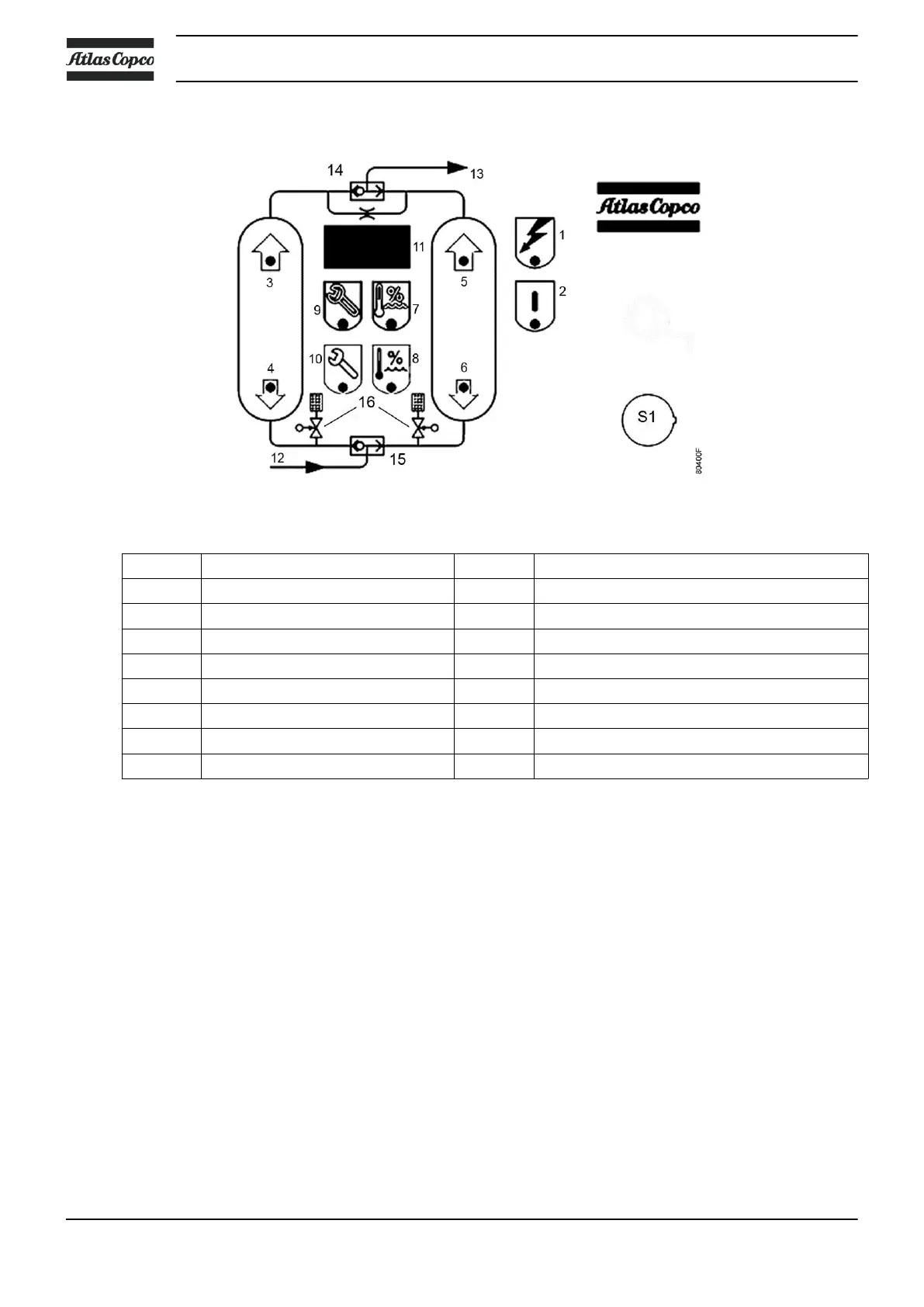
Control panel
Control panel with flow diagram
S1 On/Off switch 9 LED <Service warning>
1 LED <Power On> 10 LED <Service alarm>
2 LED <In Operation> 11 Timer countdown (Indication of PDP in option)
3 LED < Left tower drying> 12 Air Inlet
4 LED <Left tower regenerating> 13 Air Outlet
5 LED <Right tower drying> 14 Outlet selector valve
6 LED <Right tower regenerating> 15 Inlet selector valve
7 LED <PDP warning> see note 16 Solenoid valves
8 LED <PDP alarm> see note
Note: The LED indication of the dew point (PDP) (LED’s 7 and 8) is only operational when the
dryer is equipped with an electronic dew point indicator (available as option).
Instruction book
14 API093050