Instruction book
106 6996 0227 40
UL class K5 CSA
HRC from ii
I: current in the supply lines at maximum load and nominal voltage
Setting for circuit breakers
Fuse calculations for IEC are done according to 60364-4-43 electrical installations of buildings, part 4:
protection for safety- section 43: protection against over current. Fuse sizes are calculated in order to
protect the cable against short circuit.
Fuse calculations for cUL and UL: The indicated fuse size is the maximum fuse size in order to protect
the motor against short circuit. For cUL fuse HRC form II, for UL fuse class K5
Earthing
The earthing cable connected to the vacuum pump (PE) should be minimum 10 mm
2
(according to EN
60204-1 section 828).
Cable sizing according IEC
The tables below indicate the current carrying capacities of cables for 3 commonly used installation
methods, calculated according to standard 60364-5-52 - electrical installations of buildings part 5 -
selection and erection equipment and section 52 - current carrying capacities in wiring systems.
The allowed currents are valid for PVC insulated cables with three loaded copper conductors (maximum
conductor temperature 70 °C).
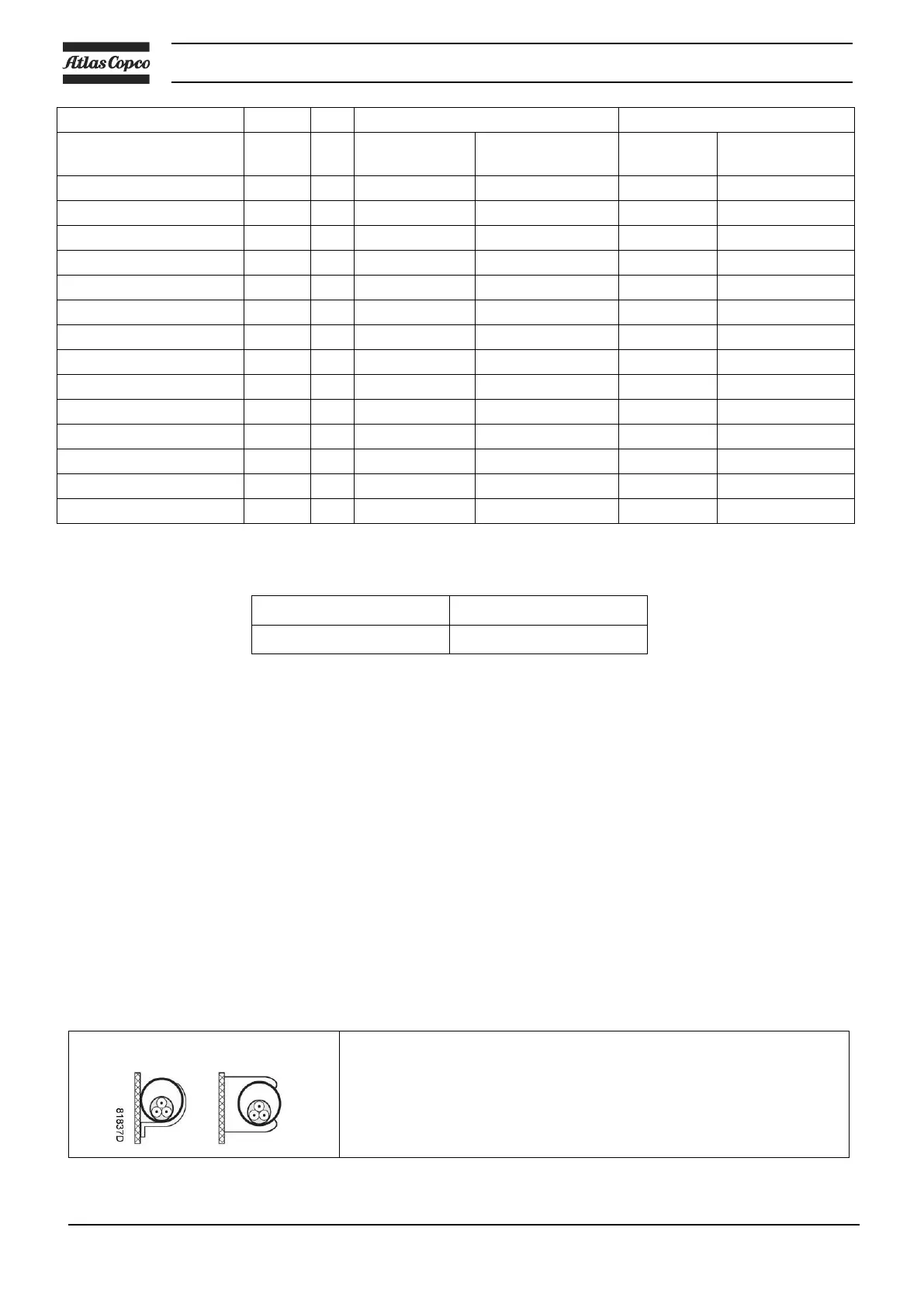
Installation method B2 according to table B.52.1. Multi-core
cable in conduit on a wooden wall.
Maximum allowed current in function of the ambient temperature for installation method B2
 Loading...