Industrial Air Division
112920 5997 03
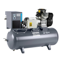
1. Valve kit
2. Filter kit
3. Check valve assembly
4. Unloader valve assembly
5. P.A.O. oil, 5 l can
Fig. 4. Preventive maintenance kits 1)
1) For correct part numbers of kits, consult ASL
(parts list)
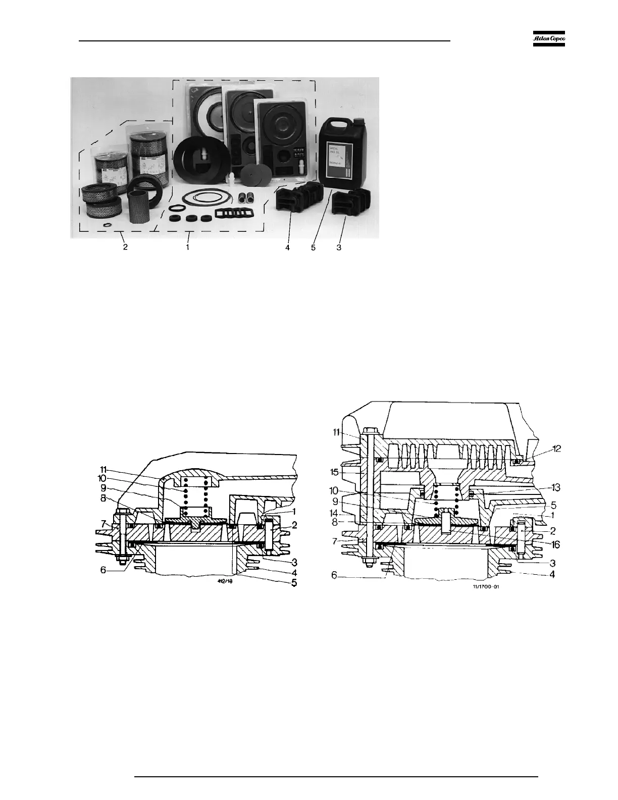
1. Rubber cord joint
2. Guide pin (2 off)
3. Rubber cord joint
4. Cylinder
5. O-ring
6. Inlet valve disk
7. Valve seat
8. Outlet valve disk
9. Outlet valve guard
10. Spiral spring
11. Cylinder head cover
12. Rubber cord joint
13. O-ring
14. Inlet cap
15. Outlet cap
16. 1) Pin
1) Outlet valve guard with central pin as drawn in Fig. 5b: only on LE9, -11, -12 and on low-pressure side of LT9, -11, -12
Figs. 5. Cylinder head valve assemblies
Fig. 5a.LE5 to -9, LE7N and low-pressure side of LT5 to -11
Fig. 5b.LE11, LE/LT12, LE9N and high-pressure side of LT5 to -11
F1760
 Loading...