Industrial Air Division
2920 5997 03
4
Fig. 1b. LT9, power pack, fan guard removed
M. Motor
PSR19. Air pressure switch
P1. Hourmeter
S1. Selector switch, operation mode
S1-I. Start button
S1-O. Stop button
Y1. Loading solenoid valve
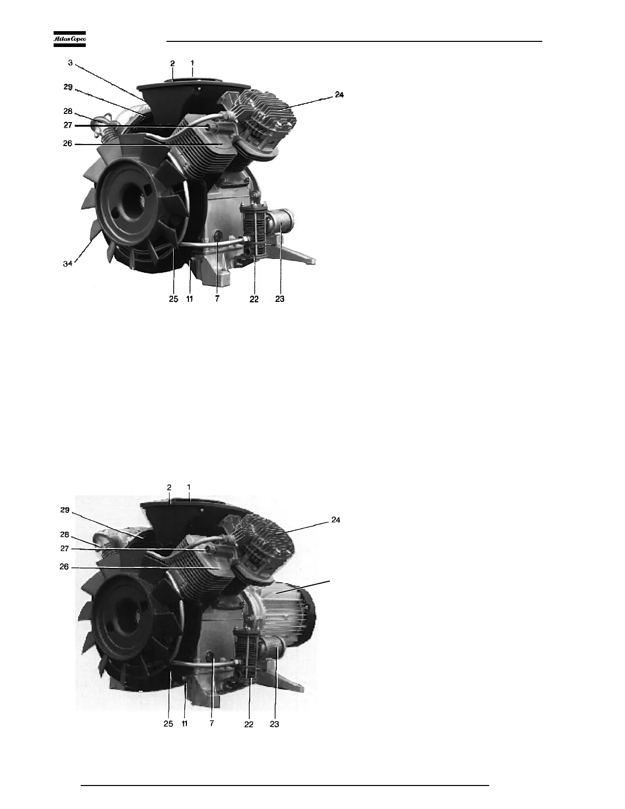
1. Oil filler cap
2. Air filter
3. Air intake silencer
4. Cylinder
5. Connecting block
6. Temperature reducer outlet
7. Oil level sight-glass
8. Check valve
9. Air receiver
10. Condensate drain cock
11. Oil drain plug
12. Safety valve
13. Air pressure gauge
14. Pressure release valve
15. Air outlet valve
16. Label, electrical diagram
17. Fan guard
18. Crankcase breather
19. Motor starter
20. Transport brackets (must be
removed)
21. Hose, compressed air from check
valve to air receiver
22. Unloader
23. Muffler
24. HP cylinder head
25. Temperature reducer
26. Pulsation damper
27. Relief valve
28. Intercooler
29. LP cylinder head
30. Air intake
31. Hinged top
32. Service panel
33. Oil drain flexible
34. Fan
Figs. 1. General views
Fig. 1a. LT9, compressor block, fan guard removed
F1753
F1754
M
 Loading...