Installation EN LSV39 SA12-125
10
© Atlas Copco Industrial Technique AB - 9839 0621 01
■
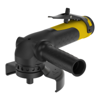
Wheel guard or Backing pad
■
Adapters, nuts or flange washers
■
Support handle
■
Throttle lever and security mechanism
■
Autobalancer
■
Spindle
Look for any damage, grease or oil leakage that can compromise the safety of the tool.
Visual inspection - air installation
Inspect the air installation visually from the supply point to the tool before use.
■
Hose
■
Couplings
■
System pressure
■
Air filter
Look for any damage that can compromise the safety of the tool.
Installation overview
Legend to page 2
A) Recommended torque
B) Hose length
C) Hose diameter
D) Max working air pressure
E) Max free speed
F) Recommended torque
G) Recommended torque
H) Spindle thread
Installation of Vibrating Tools
We recommend using a minimum length of 300 mm (12") of flexible hose for compressed air between a vi-
brating tool and the quick-action coupling.

 Loading...