Instruções de operação e de segurança PT LTP51 H
62
© Atlas Copco Industrial Technique AB - 9836 938172 72
Depois de dobrar, prenda o sinal de advertência fornecido, à barra de
reacção, ver Fig. C, e marque o lado da barra de reacção a colocar contra o
suporte de forma adequada.
3 Montagem
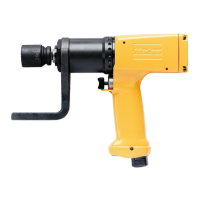
• Coloque a barra de reacção na posição desejada sobre a máquina.
• Aperte a porca a um binário de 70 Nm, 90 Nm ou 100 Nm, respectivamente.
• Verifique com regularidade se o anel de freio está firmemente seguro.
4 Uso
• Aplique a barra de reacção de acordo com a figura C – em direcção oposta à
do accionador da máquina – antes de pôr a máquina em funcionamento.
• Nunca ponha a mão sobre ou perto da barra de reacção enquanto a máquina
estiver em acção.
Table No. 1
LTP51 H006–19, LTP51 H008–13, LTP51 H012–13, LTP51 PH003–19,
LTP51 PH004–13 and LTP51 PH005–13
D = 54 mm, Wmin = 28.5 mm
Torque Nm 75 100 150 200 250
Angle α 21° 27° 37° 46° 55°
LTP51 H002–20, LTP51 H004–20, LTP51 PH001–20 and LTP51 PH002–20
D = 62 mm, Wmin = 39.5 mm
Torque Nm 250 300 400 500
Angle α 30° 35° 44° 50°
LTP51 H001–25, LTP51 PH0005–25 and LTP51 H0014-25
D = 63.5 mm, Wmin = 64.5 mm
Torque Nm 500 600 700 800 950
Angle α 32° 38° 43° 47° 53°
LTP51 H0007–25 and LTP51 PH0003–25
D = 83.5 mm, Wmin = 84.5 mm
Torque Nm 700 1000 1250 1500
Angle α 21° 30° 35° 41°
Example: LTP51 H002–20
D = 62 mm
500 Nm = 50°
 Loading...
