Safety Information LUM21 HR
8
© Atlas Copco Industrial Technique AB - 9836 1172 05
Noise (according to
PN8NTC1.2)
dB(A)
Determined sound
power level
Spread in method and
production
3
Vibration (according
to ISO 8662-7)
m/s
2
Measured vibration
value
< 2.5
Spread in method and
production
Declaration of noise and vibration
emission
These declared values were obtained by laboratory
type testing in compliance with the stated stan-
dards and are not adequate for use in risk assess-
ments. Values measured in individual work places
may be higher than the declared values. The actual
exposure values and risk of harm experienced by
an individual user are unique and depend upon the
way the user works, the workpiece and the work-
station design, as well as upon the exposure time
and the physical condition of the user.
We, Atlas Copco Industrial Technique AB, can-
not be held liable for the consequences of using the
declared values, instead of values reflecting the ac-
tual exposure, in an individual risk assessment in a
work place situation over which we have no con-
trol.
Service instructions
Service Instructions
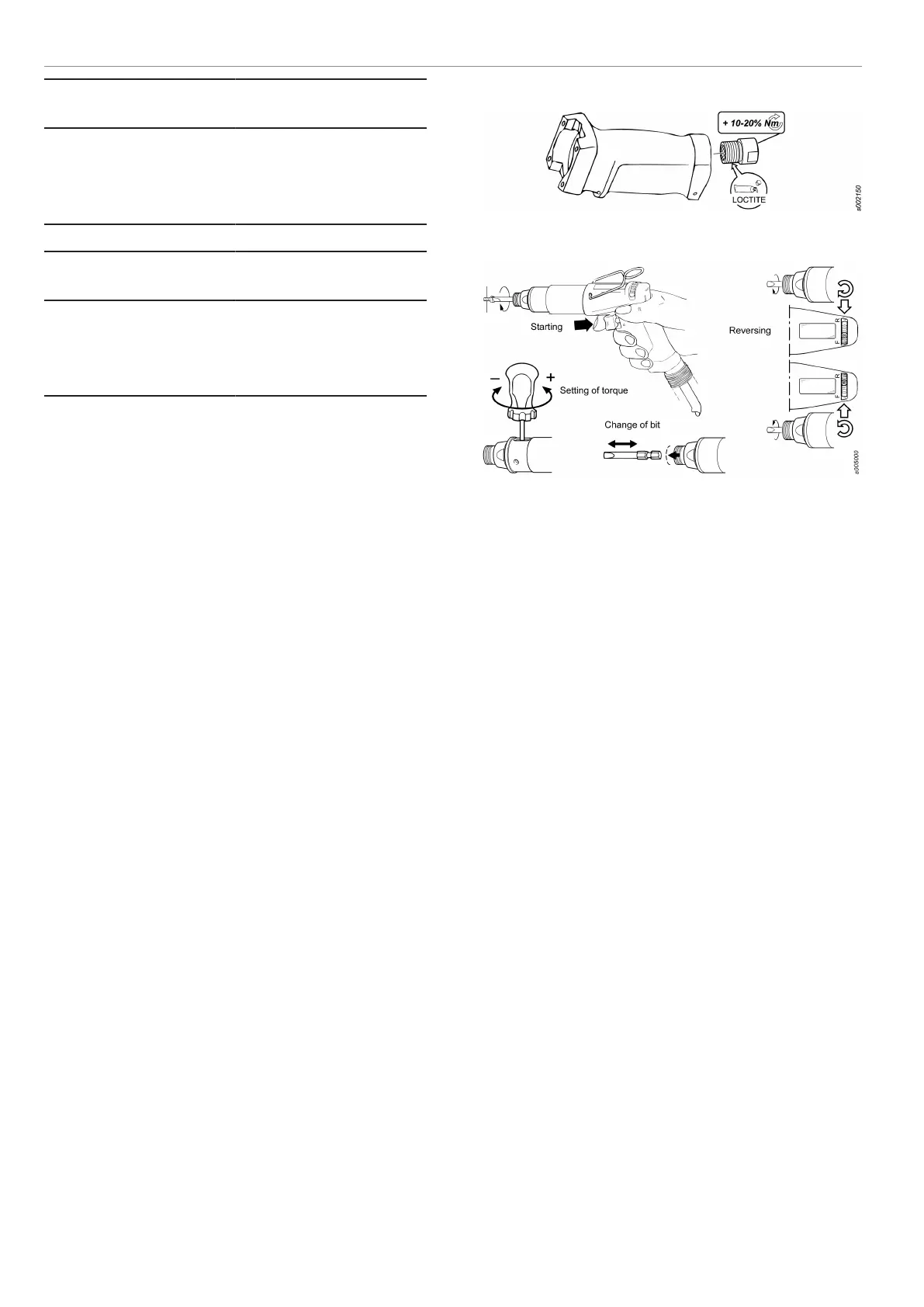
Tightening of threaded connections
The tightening torques indicated in the spare parts
list are established to achieve the correct clamping
force and to prevent the parts from coming loose.
When serviced these parts must be able to open up
without being destroyed. In special circumstances
(depending on application and usage) the parts
may however come loose after some time of opera-
tion. In such cases the torque could be increased
10-20% and if necessary some type of low or
medium threadlocking fluid could also be applied.
Example
Operating Instructions
Air pressure monitoring, RE-signal S1
Reporting pneumatic assembly tools provide a
pneumatic signal that indicates which part of the
tightening cycle the tool has reached, by means of
variations in air pressure.
In the RE-Controller box timers are triggered when
certain pressure levels are reached.
Pressure level 1 (P1) starts a timer that checks that
the tightening cycle is not too short.
Pressure level 2 (P2) starts a timer that checks the
time taken from when the clutch has been released
to when the operator releases the trigger to ensure
that it is not too short.
The controller measures the differential pressure
over the motor.
It should be noted that the system does not mea-
sure torque! Regular check of installed torque/
torque output of the tool must be done separately.
The RE-Controller checks the air-line pressure.
One of the most common problems in air-line sys-
tems is pressure variations. If the pressure drops
too much the tool might stall and/or the torque will
not be correct. The RE-Controller will give a sig-
nal if the pressure drops too much.
 Loading...