38 2954 2100 01
QAS 14 - 20 Pd
7.3.11 IT-relay
The generator is wired for an IT network i.e. no supply lines of the
power supply are directly earthed. A failure in insulation resulting
in a too low insulation resistance, is detected by the insulation
monitoring relay.
Q1 ..... Circuit breaker for X1.1
Interrupts the power supply X.1.1 when a short-circuit occurs
at the load side, or when the overcurrent protection (QAS 14:
20 A, QAS 20: 32 A) is activated. When activated, Q1
interrupts the three phases towards X1. It must be reset
manually after eliminating the problem.
X1.1... Main power supply (400 V AC)
Terminals L1, L2, L3, N (= neutral) and PE (= earthing),
hidden behind the control panel door and behind a small
transparent door.
N14 ... Insulation monitoring relay
Checks the insulation resistance and activates Q1 when the
insulation resistance is too low.
S2...... Emergency stop button
Push the button to stop the generator in case of an emergency.
When the button is pressed, it must be unlocked, by turning it
anti-clockwise, before the generator can be restarted. The
emergency stop button can be secured in the locked position
with the key, to avoid unauthorized use.
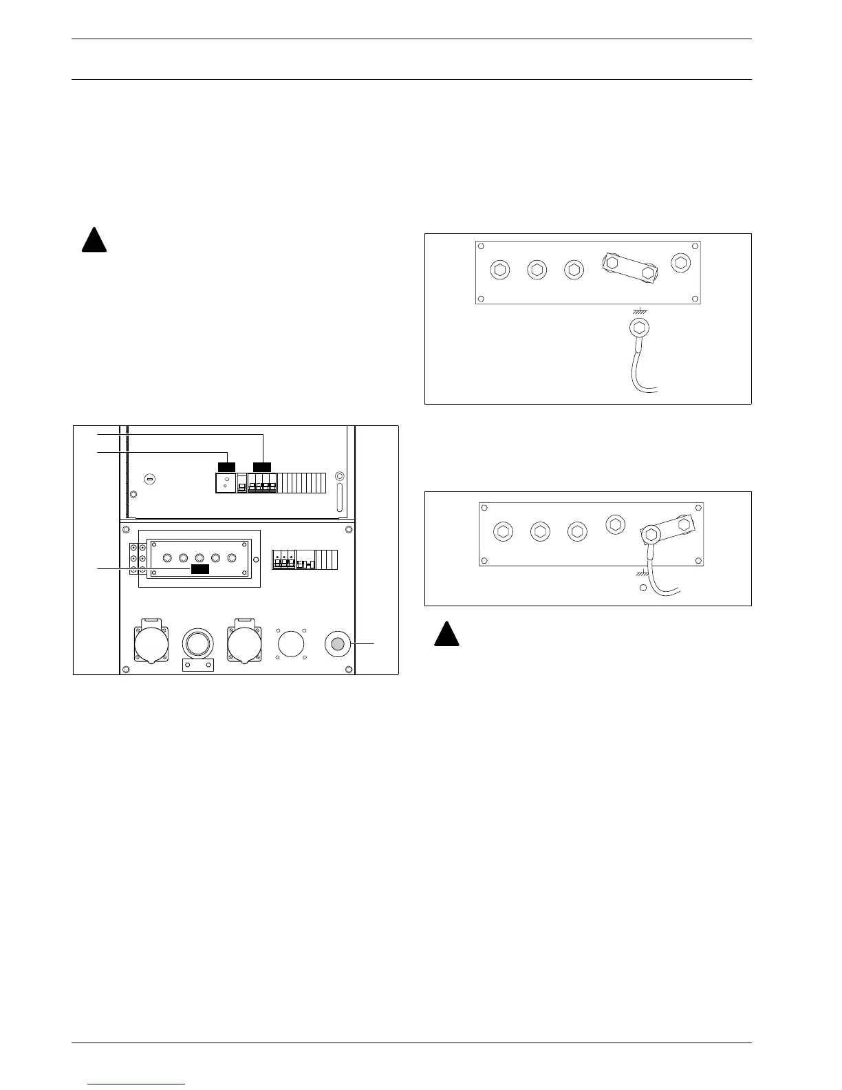
7.3.12 “Electricité de France” (EDF)
When the EDF-option is installed, the unit operates as a standard
unit when the neutral and the PE terminals are connected to each
other (see figure below). In this case, an earth leakage at the side of
the generator or at the side of the load will switch off the circuit
breaker.
When EDF-option is installed, the unit operates as EDF-unit when
the earthing, the PE and the PE EDF terminals are connected to
each other (see figure below). In this case, an earth leakage at the
side of the generator will switch off the circuit breaker. An earth
leakage at the side of the load will not switch off the circuit breaker.
7.3.13 Refinery equipment pack
This refinery equipment option consists of :
– Integrated spark arrestor
– Engine air inlet shut-off valve
Air inlet shut-off valve
The engine air inlet shut-off valve option will prevent over-
speeding of the engine due to combustible gases being traced
within the normal engine air intake.
The generator shall not be operated with other net-
works (such as TT or TN). Doing so will cause trip-
ping of the insulation monitoring relay.
The generator is wired for an IT network i.e. no sup-
ply lines of the power supply are directly earthed. A
failure in insulation resulting in too low an insula-
tion resistance, is detected by the insulation monitor-
ing relay.
At each start-up and any time a new load is con-
nected, the insulation resistance must be verified.
Check for the correct setting of the insulation moni-
toring relay. (factory set at 13 k
Ω)
!
N14 Q1
X1.1
S2
Q1
X1.1
N14
Changing the operation mode from standard unit to
EDF-unit or vice versa has to be carried out by a
qualified person from “Electricité de France”.
L1 L2 L3
N PE EDF
PE
L1 L2 L3
N PE EDF
PE
!

 Loading...


