38 2954 2380 00
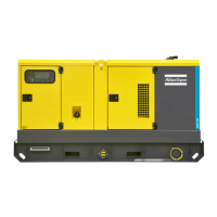
QAS 80 - 100 Pd
7. Options available for QAS 80 Pd and QAS 100 Pd units
7.1 Circuit diagrams
The engine control circuit diagrams and the power circuit diagrams
for the standard QAS 80 Pd and QAS 100 Pd units:
Unit Power circuit Engine control circuit
QAS 80 - 100 Pd Qc1001™ 9822 0992 20 9822 0992 18
QAS 80 - 100 Pd Qc3001™ 9822 0992 20 9822 0992 19
QAS 80 - 100 Pd Low voltage 9822 0992 21
7.2 Overview of the electrical options
The following “electrical” options are available for the QAS 80 Pd
and QAS 100 Pd units:
– Automatic battery charger
– Battery switch
– Engine coolant heater
– Outlet sockets (S)
– Single frequency with electronic speed control (SF)
– Dual frequency with electronic speed control (DF)
– Electronic speed regulator
– Low voltage (LV)
– Single phase (1 Ph)
– Earth leakage relay
– IT-relay
– Refinery equipment pack
7.3 Description of the electrical options
7.3.1 Automatic battery charger
The “trickle charger” charges the battery completely and is
disconnected once the unit starts up.
Besides the output terminals (secondary side) the automatic battery
charger has a trim potentiometer for setting of the output voltage.
By means of an insulated slotted screwdriver or adjusting pin the
output voltage can be set in the range.
The LED on the front indicates that the unit is operational.
Setting:
– Lower output voltage = Counterclockwise rotation
– Higher output voltage = Clockwise rotation
To use the batery charger:
– Provide the X25 connector, located at the side of the power cubicle,
with external power to use the battery charger.
7.3.2 Battery switch
The battery switch is situated inside the sound-insulated bodywork.
It allows to open or to close the electrical connection between the
battery and the engine circuits.
7.3.3 Engine coolant heater
To make sure that the engine can start and accept load immediately,
an external coolant heater (1000 W, 240 V) is provided which
keeps the engine temperature between 38°C and 49°C.
Never turn the battery switch to OFF during
operation.
DEIF
-power in control
xxxx xxxx xxxxxx
xxxx
xxxx
xxxxxxxx
xxxx
xxxxxxxxxxx
xxxxxxxxxxxxxxxx
xxxxxxxxxxxxxxx
xxxxxxxxxxxxxx
!
!

 Loading...