QAS38 YdS TNV
10 2954 9020 00
2.5.2 Generator gauges
P1...... Ammeter line L1
Indicates the outgoing current in the first line (L1).
P2...... Ammeter line L2
Indicates the outgoing current in the second line (L2).
P3...... Ammeter line L3
Indicates the outgoing current in the third line (L3).
P4...... Voltmeter
Indicates the voltage selected by means of voltage selector
switch S4.
P5...... Frequency / RPM meter
Indicates the frequency of the supply voltage and the speed of
the engine.
S4...... Voltmeter selector switch
Allows to measure the voltage between each of the phases and
between each phase and the neutral. It also allows to switch off
the voltmeter.
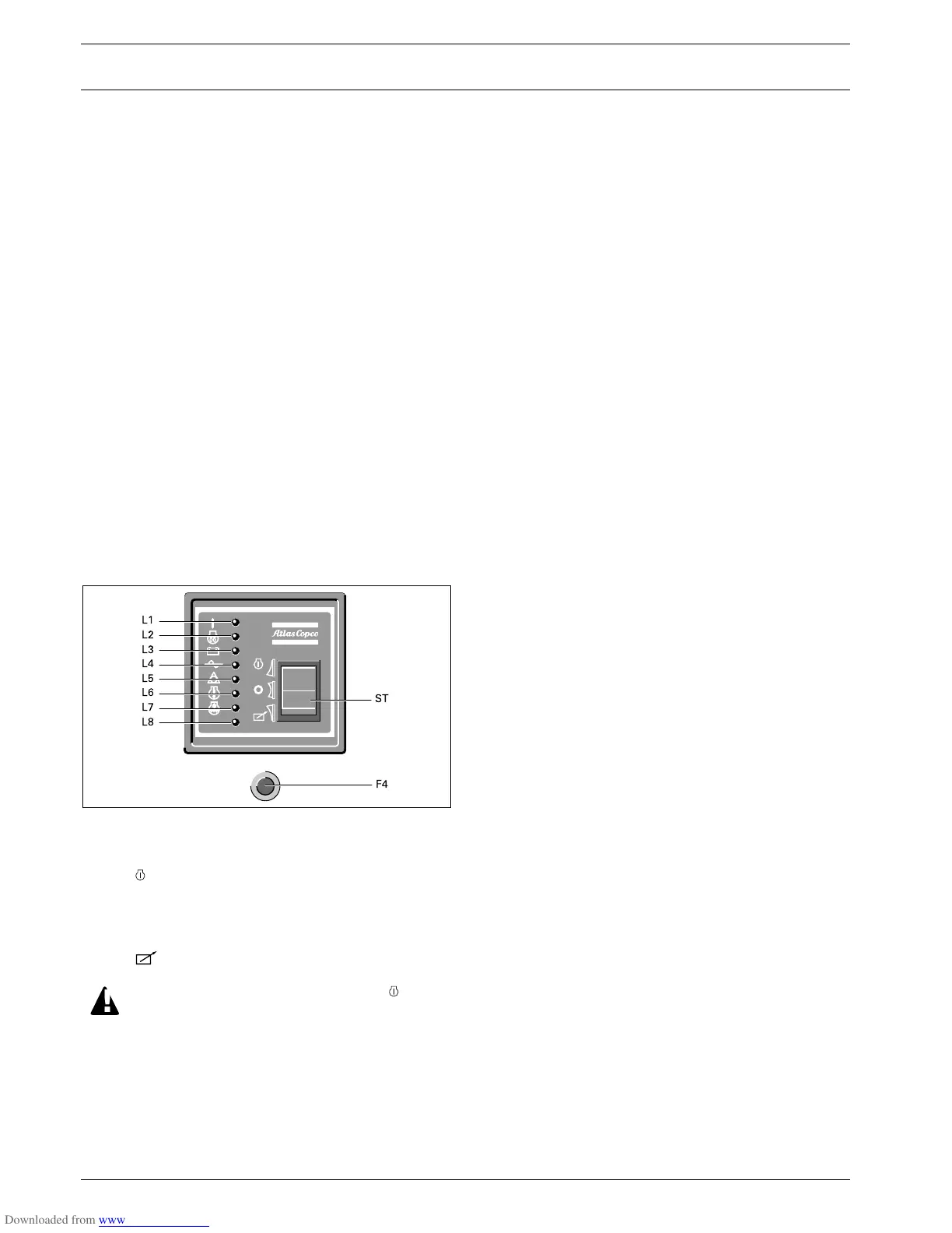
2.5.3 Engine controls and lamps
ST...... Starter switch
The starter switch is a three-position switch.
– : used to select normal start and to disable remote start
– O : used to switch off the power supply from the battery
or to reset after a shut down due to a failure. The unit
will not be able to start up.
– : used to select remote start.
F4 ...... Fuse
The fuse activates when the current from the battery to the en-
gine control circuit exceeds its setting. The fuse can be
switched on and off by pushing the button.
L1 ...... Electrical system indicator
Lights up when the electrical system of the engine is energized.
L2 ...... Engine preheating system indicator
Lights up when the glow plugs in the engine, used to facilitate
starting, are warming up. Extinguishes after approximately 10
seconds. Bypassing of the preheattime is allowed e.g. when
starting a hot engine, but the preheat system remains active.
L3 ...... Alternator charging indicator
Goes out after starting, indicating that the alternator is charg-
ing. A failing alternator however will not shut the engine down.
L4 ...... AC shut down indicator
Lights up when no AC input (< 75 V line-to-neutral) is present.
L5 ...... Overspeed shut down indicator
Lights up when the engine’s speed has exceeded 115 % of the
nominal speed.
L6 ...... Engine coolant temperature fault indicator
Lights up when the high engine coolant temperature was the
cause of shut down.
L7 ...... Engine oil pressure fault indicator
Lights up when the low engine oil pressure was the cause of
shut down.
L8 ...... Spare shut down indicator
Can be used to wire an extra shut down, e.g. for low fuel level
in case a switch is incorporated in the fuel tank.
R11.... Output voltage adjust potentiometer
Allows to adjust the output voltage. R11 is located on the con-
trol and indicator panel.
After approximately 20 seconds in position with-
out starting, the control system will automatically
shut down (battery saving purpose) indicating a low
oil pressure failure. In this case, a reset of the control
system by putting the switch in position O is neces-
sary.
F4
L1
L2
L3
L4
L5
L6
L7
L8
ST
 Loading...


