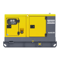
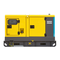
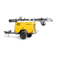
QAS38 YdS TNV
14 2954 9020 00
3.4 Starting
To start up the unit locally, without using the re-
mote start/stop switch, proceed as follows:
– Put the starter switch in position . The unit starts a preheating cy-
cle which takes 12 seconds.
– After the preheating period, the unit will start. The starting attempt
will take maximum 12 seconds. If the unit does not start immediate-
ly, it will perform another two starting attempts.
– Approximately 15 seconds after starting (stabilization time for the
generator), the timer relay closes the voltage free contact and the
plant contactor is energized (if installed).
– Check that the warning lamps on the control and indicator panel are
out. Refer to “Control and indicator panel” for component locations.
– Run the engine for approximately 5 minutes to warm up.
– Check the engine oil pressure (P9) and the cooling water tempera-
ture (P8).
– Check the voltmeter P4 (with voltmeter selector switch S4 in differ-
ent positions) and the frequency meter P5.
– Switch on circuit breaker Q1.1 or Q1.2, depending on the mode the
generator is running in.
– Switch on the load and check the ammeters P1, P2 and P3, voltmeter
P4 (voltmeter selector switch S4 in different positions) and the fre-
quency meter P5.
To start up the unit from a remote location using
the remote start/stop switch, proceed as follows:
– Put the starter switch in position .
– Switch on circuit breakers Q1.1 or Q1.2, depending on the mode the
unit is running in.
– Put the remote start/stop switch in position start. The unit starts a
preheating cycle which takes 12 seconds.
– After the preheating period, the unit will start. The starting attempt
will take maximum 12 seconds.
– Approximately 15 seconds after starting (stabilization time for the
generator), the timer relay closes the voltage free contact and the
plant contactor is energized (if installed).
– Check that the warning lamps on the control and indicator panel are
out. Refer to “Control and indicator panel” for component locations.
– Run the engine for approximately 5 minutes to warm up.
– Check the engine oil pressure (P9) and the cooling water tempera-
ture (P8).
– Check the voltmeter P4 (with voltmeter selector switch S4 in differ-
ent positions) and the frequency meter P5.
– Switch on the load and check the ammeters P1, P2 and P3, voltmeter
P4 (voltmeter selector switch S4 in different positions) and the fre-
quency meter P5.
3.5 During operation
Following points should be carried out regularly:
– Check the engine gauges and the lamps for normal readings.
– Check for leakage of oil, fuel or cooling water.
– Avoid long low-load periods (< 30 %). In this case, an output drop
and higher oil consumption of the engine could occur.
– Check, by means of the generator gauges, that the voltage between
the phases is identical and that the rated current per phase is not ex-
ceeded.
– When single-phase loads are connected to the generator output ter-
minals, keep all loads well-balanced (in 3 phase output voltage
mode).
– If circuit breakers are activated during operation, switch off the load
and stop the generator. Check and, if necessary, decrease the load.
3.6 Stopping
To stop the unit when the starter switch is in posi-
tion , proceed as follows:
– Switch off the load.
– Switch off circuit breakers Q1.1 or Q1.2, depending on the mode the
unit is running in.
– Let the engine run for about 5 minutes.
– Stop the engine by putting the starter switch in position O.
To stop the unit when the starter switch is in posi-
tion , proceed as follows:
– Switch off the load.
– Let the engine run for about 5 minutes.
– Stop the engine by putting the remote start/stop switch in position
stop or by putting the starter switch in position O.
Avoid to let the engine run out of fuel. If it hap-
pened, priming will speed up the starting.
The generator’s side doors may only remain opened
for short periods during operation, to carry out
checks for example.
Lock the side doors and the door of the indicators
and control panel to avoid unauthorized access.

 Loading...
