Observe all the applicable national and regional
regulations on securing loads.
Installation
Before installing the hydraulic breaker on the carrier
or operating it, read the operation manual and safety
instructions provided by the carrier manufacturer.
Follow all instructions.
The carrier must have the appropriate hydraulic
system for operation of the breaker.
If the carrier is too large for the hydraulic breaker it
may lead to broken working tools and increased
wear. See "Technical data" for choosing suitable
carrier.
The safety equipment in the hydraulic system must
be checked for quality (CE mark, etc.), suitability and
functionability by a professional or authorised
supervisor before use.
Hoses and connections
WARNING Whipping hydraulic hose
Hydraulic hoses under pressure can whip
uncontrollably if screws loosen or are loosened. A
whipping hydraulic hose can cause severe injuries.
► Depressurise the hydraulic system before
loosening the connection of a hydraulic hose.
► Tighten the nuts on the connections of the
hydraulic hoses to the required torque.
Type of nipple: ORFS standard nipple. The nipple
dimensions can be found in the Spare parts list.
The quality of the hydraulic hoses must be 2SC
(according to EN 857) or better when connecting the
breaker to the carrier. If quick couplings are to be
used, we recommend using the 'Flat Face' quick
coupling. This type is sturdy and easy to clean. The
quick coupling pressure class must agree with the
carrier's working pressure.
Always clean the quick couplings before mounting
or dismounting. Always plug hoses and hose nipples
with tight and clean end caps when dismounting.
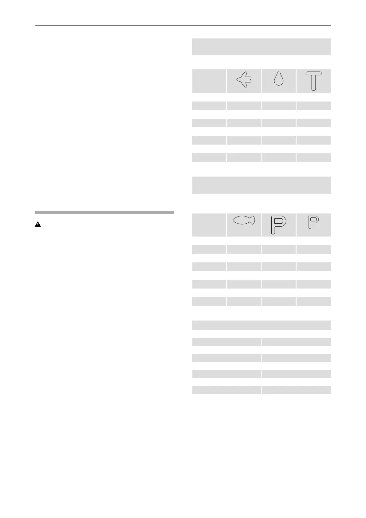
Hose connections
Right (As seen from operator’s seat)
Tank, return
line
Central
lubrication
Air flushing
Symbol
G
3
⁄
8
in.G
1
⁄
4
in.G
1
⁄
4
in.SB 52
G
1
⁄
2
in.G
1
⁄
4
in.G
1
⁄
4
in.SB 102
G
1
⁄
2
in.G
1
⁄
4
in.G
1
⁄
4
in.SB 152
G
1
⁄
2
in.G
1
⁄
4
in.G
1
⁄
4
in.SB 202
G
3
⁄
4
in.G
1
⁄
4
in.G
1
⁄
4
in.SB 302
G
3
⁄
4
in.G
1
⁄
4
in.G
1
⁄
4
in.SB 302 SC
G
3
⁄
4
in.G
1
⁄
4
in.G
1
⁄
4
in.SB 452
G
3
⁄
4
in.G
1
⁄
4
in.G
1
⁄
4
in.SB 452 SC
G 1 in.G
1
⁄
4
in.G
1
⁄
4
in.SB 552
Hose connections
Left (As seen from operator's seat)
Pressure for
ContiLube II
micro
Pressure to
breaker
Water
Symbol
G
1
⁄
4
in.G
3
⁄
8
in.-SB 52
G
1
⁄
4
in.G
1
⁄
2
in.-SB 102
G
1
⁄
4
in.G
1
⁄
2
in.G
1
⁄
4
in.SB 152
G
1
⁄
4
in.G
1
⁄
2
in.G
1
⁄
4
in.SB 202
G
1
⁄
4
in.G
3
⁄
4
in.G
1
⁄
4
in.SB 302
G
1
⁄
4
in.G
3
⁄
4
in.G
1
⁄
4
in.SB 302 SC
G
1
⁄
4
in.G
3
⁄
4
in.G
1
⁄
4
in.SB 452
G
1
⁄
4
in.G
3
⁄
4
in.G
1
⁄
4
in.SB 452 SC
G
1
⁄
4
in.G 1 in.G
1
⁄
4
in.SB 552
Tightening torque for pressure and return hoses
60 NmSB 52
150 NmSB 102
150 NmSB 152
150 NmSB 202
210 NmSB 302
210 NmSB 302 SC
210 NmSB 452
210 NmSB 452 SC
300 NmSB 552
NOTICE The tightening torques in the table above
are valid when the pressure and return hose are
mounted directly on the hydraulic breaker's
connection nipple. If the pressure and return hose
are connected with an additional connection nipple,
another tightening torques must be used.
13© 2014 Construction Tools PC AB | No. 9800 0648 01l | 2014-06-11
Original instructions
Safety and operating instructionsSB 52, 102, 152, 202, 302, 302 SC, 452, 452 SC, 552
 Loading...