+05647%6+10/#07#.
17
5
6#46+0)
5
6122+0)
)
'0'4#.
PGLV H5 H6 H7 S
F1
0
000
H1 H2 H3 H4 N4
P1
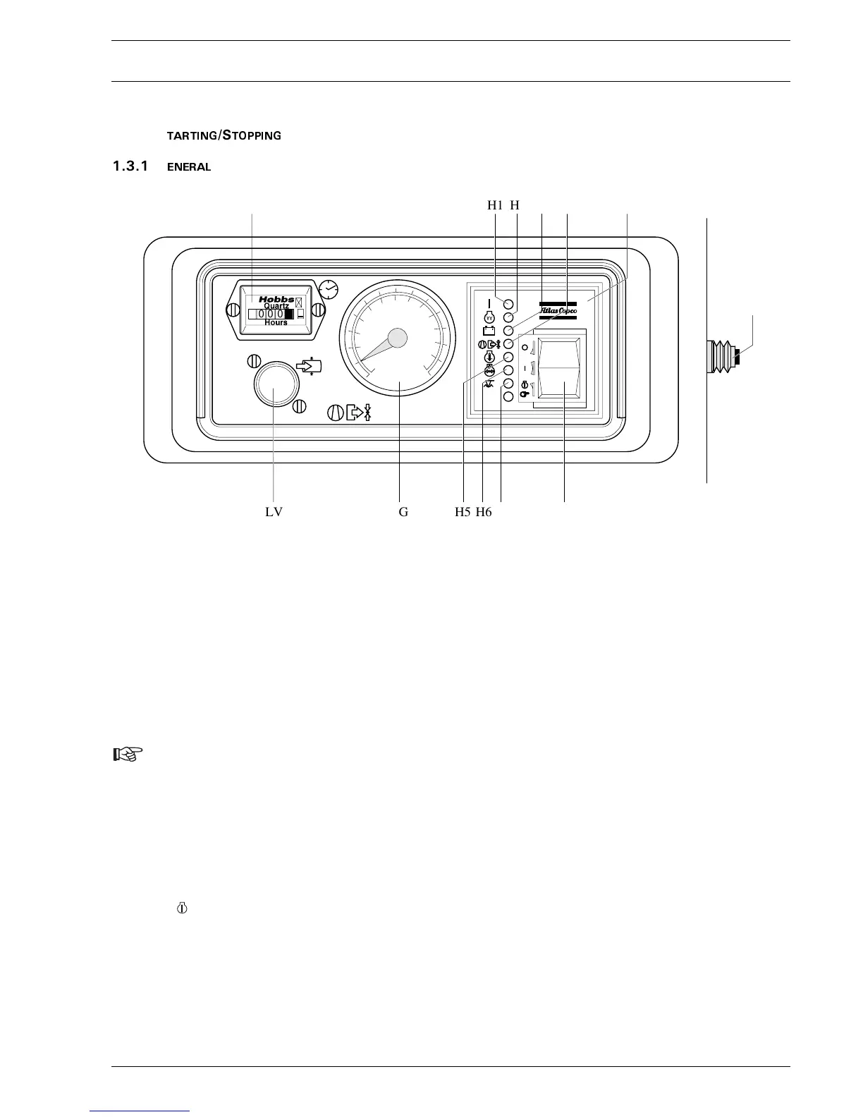
Make sure the fuel tank is filled up.
Before starting, first operate the circuit breaker button (F1) at the right
side of the control panel (open right-hand service door first).
To start, the start/stop button (S) is switched to position ”I”, the green
fuel ON lamp (H1), the red charge indication lamp (H3) and preheat
lamp (H2) go on (preheat lamp only, if ”cold start” option is installed).
After preheating, the preheat lamp goes out. Push the start/stop button
in position ” ”. 20 sec. cranking, 1 min. rest (= a cycle). Max. 3
cycles are allowed. The starter motor will set the engine in motion.
Lamps H1 and H3 will go out as soon as the engine has been started.
After the start/stop button is released, it automatically springs back to
position ”I”.
Run the engine a few minutes at no-load to warm up.
When the engine is running smoothly, press loading valve (LV) and
release as soon as pressure starts to build up.
Shutting down is simply done by pushing the start button in the ”0”
position.
The control panel in addition indicates receiver pressure (PG) and
accumulated operating hours (P1).
)DXOWVLWXDWLRQVDQGSURWHFWLYHGHYLFHV$OVRUHIHUWRFKDSWHU
3UREOHP6ROYLQJ
– The starter motor is protected against prolonged starting or
against attempts to start when the unit is already running.
(max. cranking time: 20 sec.)
– A fault which occurs with the engine, either alternator voltage
(too low), coolant temperature (too high), oil pressure too low,
coolant level too low or fuel level too low will always and
immediately cause the engine to cut out and one of the control
lamps H3, H5, H6 or H7 to light up.
– When the outlet temperature of the element becomes too high, a
thermocontact will also switch off the unit immediately.
Control lamp H4 will light up.
– The control lamps will remain on untill the unit has been reset
(start button switched to position ”0”).
:KHQWKHXQLWLVSXWLQ RS HUDW LRQI R UWK HILUVW WLPHDQG
DIWHUUXQQLQJRXWRI I XHORUFKDQJLQJWKHI XHOILOWHU
IROORZ WKHVSHFLILFVWDUWSUR FHGXU HDVGHVFULEHGLQ
VHFWLRQ
P1 Hourmeter
F1 Circuit Breaker Button
PG Working Pressure Gauge
LV Loading Valve
N4 Control Module
S Start/Stop Button
H1 LED (green) Fuel ON
H2 LED (green) Preheat (option)
H3 LED (red) Charge Indication
H4 LED (red) Compressor Outlet Temperature
H5 LED (red) Engine Coolant Temperature
H6 LED (red) Engine Oil Pressure
H7 LED (red) Low Coolant
Fig. 3.10 Control panel
 Loading...