Do you have a question about the Atlas AC-105 and is the answer not in the manual?
Key technical details of the AC-105 lift, including load capacity, speed, drive type, motor, and standards.
Essential disclaimers, important notes, and warnings regarding the installation guide and product.
Definitions for safety alert levels (DANGER, WARNING, CAUTION, NOTE) used throughout the guide.
Critical safety precautions and disclaimers to follow before and during the installation process.
Essential requirements including codes, site preparation, and electrical needs before starting installation.
Overview of the rail system components including upper, middle, and lower rails and their layout.
Detailed measurement instructions for the lower rail system installation.
Steps for aligning and mounting the lower rail to wall studs or posts using lag screws.
Process for joining subsequent lower rails and ensuring proper clearance from the lower landing floor.
Instructions for measuring the 18" distance and mounting the upper rail to wall studs/posts.
Method for joining multiple upper rail sections using rail joints and hex bolts.
Steps for measuring the 5-1/4" distance and mounting the middle rail to wall studs/posts.
Instructions for joining middle rail sections, noting they do not require rail joints.
Procedure for mounting the tower column to the upper and lower rails using provided brackets and hardware.
Steps to screw the tower to the wall or post at the upper and lower screw entry points.
Steps to install the platform piston with ball joint and locking clip before unfolding the platform.
Instructions to remove upper and lower carriage covers by unscrewing the specified screws.
Guide to mounting upper rollers, including orientation and brake placement, onto the upper rail.
Steps for positioning the carriage at the bottom landing and sliding it onto the rails, ensuring roller alignment.
Critical steps for ensuring correct lower roller gap and fastening the carriage to upper rollers.
Procedure for installing the RR .50 chain, running it along the rail, and tightening to remove slack.
Steps for routing the drive motor power cable through the drag chain cable carrier and securing it to the rails.
Instructions for wiring the main power supply to the electrical disconnect and the drive motor to the ECP.
Steps for wiring the four batteries to the ECP, including their orientation and placement.
Procedure for loosening set screws, sliding security arms onto D-shafts, and fastening them.
Verifying that the safety arms' cams are properly adjusted as per factory settings for correct operation.
Ensuring that the floor cams have been properly adjusted for correct functionality.
Determining cam position for limit switches and installing them on the lower rail using screws and nuts.
Critical warning to ensure cams are installed facing inward towards the carriage for proper operation.
Instructions for mounting the upper tower cover and the two carriage covers using the specified screws.
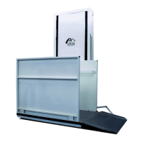
The Atlas AC-105 is an Inclined Platform Lift designed for mobility and accessibility, suitable for both residential and commercial applications. This device provides a smoother and more stable ride due to its unique C-shaped rail system. The platform is designed to fit most staircases and can be folded when not in use, offering a compact and quiet solution. A notable feature is that it does not require a separate mechanical room, as all components are integrated into the sleek and slim upper landing column.
The AC-105 Inclined Platform Lift is designed to transport individuals, particularly those using mobility devices, up and down staircases. It operates along a rail system mounted to a supporting wall, posts, or floor. The platform itself is foldable, allowing it to be stowed away when not in use, thus minimizing its footprint in the living space. The lift is powered by a 24 VDC motor and utilizes a sprocket and chain drive type for movement along the rails. Safety is a primary concern, with features like safety arms and calibrated cams to ensure secure operation. The installation process involves mounting multiple rail sections (lower, middle, and upper), installing the upper tower column, preparing the platform by installing the platform piston, and then mounting the carriage with its rollers. The drive chain and cable carrier are then installed, followed by the electrical wiring for the main power, drive motor, and batteries. Finally, safety arms are installed and calibrated, floor cams are adjusted, rail cams and limit switches are set, and the covers for the upper tower and carriage are mounted.
The Atlas AC-105 is designed for authorized dealers to install and service, ensuring that the device is set up correctly and safely according to manufacturer specifications and local regulations. Failure to comply with installation instructions can void the Atlas Limited Warranty.
| Brand | Atlas |
|---|---|
| Model | AC-105 |
| Category | Lifting Systems |
| Language | English |