Do you have a question about the Atmel ATmega168 and is the answer not in the manual?
Overview of the ATmega168 Xplained Mini evaluation board's capabilities.
Links to relevant documents and software for the evaluation board.
Information on how to assemble the Xplained Mini board for various uses.
Instructions on how to connect the evaluation board.
Guide to connecting the ATmega168 Xplained Mini to Atmel Studio.
Steps to connect the ATmega168 UART to the PC via mEBDG COM port.
Guidance on how to program and debug the Xplained Mini board.
Instructions for programming the ATmega168 via the SPI bus using mEDBG.
Steps for debugging the ATmega168 using the onboard mEDBG debugger.
How to program the ATmega168 using external AVR programmers like JTAGICE.
Instructions for programming the ATmega32U4 with external programmers.
Guide on how to use the bootloader to program the ATmega32U4.
Steps to download and install the FLIP tool for bootloader programming.
Information on the demo program and source code availability.
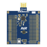
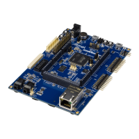
Visual overview of the ATmega168 Xplained Mini board and its components.
Details on the clock sources and distribution for the ATmega32U4 and ATmega168.
Description of the various headers and connectors on the board.
Details about the JTAG programming header (J100).
Information on the USB 2.0 connector (J101) for PC connection.
Details on the UART signals available on the J102 connector.
Mapping of ATmega168 digital I/O pins to connectors J200 and J201.
Details on the ATmega168 analogue I/O pins accessible via J203.
Information regarding VCC and RESET signals available on J202.
Details on the ISP connector (J204) for programming and SPI connection.
Overview of the Graphical User Interface elements on the board.
Description of the LEDs (D100, D200) and their functions.
Information about the user-accessible button (SW200) and its function.
Details about the preprogrammed demo program and mEDBG firmware.
| Architecture | AVR |
|---|---|
| CPU | 8-bit AVR |
| Flash Memory | 16 KB |
| SRAM | 1 KB |
| EEPROM | 512 Bytes |
| Operating Voltage | 1.8 - 5.5 V |
| Digital I/O Pins | 23 |
| PWM Channels | 6 |
| ADC Channels | 8 |
| Timers | 3 |
| Clock Speed | 20 MHz |
| Category | Microcontroller |
| Core | AVR |
| Bit Size | 8-bit |
| Communication Interfaces | USART, SPI, I2C |
| Package | TQFP |
| Manufacturer | Microchip Technology |